
Designing secure and efficient authentication flows requires more than just writing code. It demands a clear visual representation of logic, decision points, and user interactions. An Activity Diagram serves as the blueprint for these processes, translating abstract requirements into a structured workflow. In this guide, we will dissect a complex login system, breaking down every node, fork, and decision point to ensure robust modeling.
🎯 Why Visualize Authentication Logic?
Authentication systems are the gatekeepers of digital resources. A single error in logic can lead to security vulnerabilities or poor user experiences. By mapping the workflow using an Activity Diagram, stakeholders can identify bottlenecks, verify error handling, and ensure that every edge case is accounted for before development begins.
- Clarity: Developers and non-technical stakeholders understand the flow without reading code.
- Validation: Logic gaps become visible during the modeling phase.
- Documentation: The diagram acts as living documentation for future maintenance.
- Security: Ensures sensitive steps like token generation are properly sequenced.
🛠️ Prerequisites for Modeling
Before drawing the first node, it is essential to define the scope and actors involved. A login system is not merely a button click; it involves multiple systems interacting behind the scenes.
Key Actors & Components
- User: The individual initiating the login attempt.
- Frontend Interface: The form or screen capturing credentials.
- Authentication Service: The backend logic verifying identity.
- Database: The storage for user credentials and session data.
- Security Module: Handles hashing, encryption, and token issuance.
🗺️ Step-by-Step Mapping Process
We will now construct the diagram logically, moving from the initial entry point to the final session establishment. Each section below corresponds to a specific cluster of nodes in the diagram.
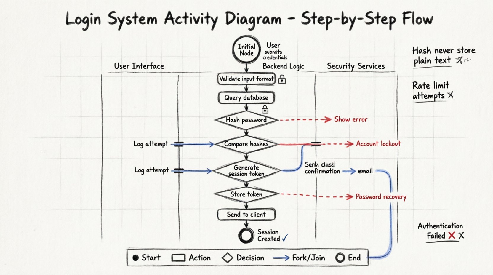
1. The Initial Node 🚦
Every activity diagram begins with a solid black circle. This represents the start of the process. For a login system, this occurs when the user navigates to the login page or initiates the authentication request.
- Action: User submits credentials.
- Output: An arrow leading to the first processing action.
2. Input Validation & Capture 🔍
Once credentials are submitted, the system must verify the format before querying the database. Sending malformed data to a database is inefficient and potentially risky.
- Username Check: Is the field empty? Is the format valid?
- Password Check: Minimum length requirements met? Special characters included?
- Guard Conditions: Use diamonds to represent these checks. Label edges with conditions like
[valid format]or[invalid format].
3. Database Query Logic 🔐
If validation passes, the system proceeds to verify the credentials against stored data. This is a critical action node.
- Action: Retrieve user record.
- Decision: Does the record exist?
- Path A: Record not found. Redirect to error state.
- Path B: Record found. Proceed to password verification.
4. Password Verification 🔒
Never compare raw passwords. The system must hash the input and compare it to the stored hash.
- Action: Hash the input password.
- Decision: Does the hash match the stored hash?
- Success Path: Proceed to session management.
- Failure Path: Log the attempt and redirect to retry.
5. Session Management & Token Generation 🎫
Upon successful authentication, the system must establish a session. This involves creating a unique identifier and setting expiration parameters.
- Action: Generate Session Token.
- Action: Store Token in Database.
- Action: Send Token to Client (via HTTP-only cookie or header).
- Security Note: Ensure the diagram reflects that the token is transmitted securely.
6. Error Handling & Retries ⚠️
A robust system anticipates failure. We must model what happens when authentication fails multiple times.
- Counter Logic: Track failed attempts.
- Threshold: If attempts exceed a limit, trigger account lockout.
- Notification: Alert the user or security team.
- Reset Mechanism: Allow the user to initiate a password recovery flow.
📑 Node Types & Usage Table
To ensure clarity in your diagram, use the standard UML symbols correctly. The table below outlines which shapes to use for specific logical functions.
| Shape | Symbol | Usage Context | Example in Login Flow |
|---|---|---|---|
| Initial Node | ● | Start of the workflow | User clicks Login button |
| Activity Node | Rounded Rectangle | Processing action | Hash password, Query DB |
| Decision Node | ⬡ | Branching logic | Is password correct? |
| Fork Node | Bar (Thick) | Parallel processing | Log attempt AND Send Email |
| Join Node | Bar (Thick) | Convergence of paths | After logging AND emailing |
| Final Node | ● (Double Ring) | End of workflow | Session Created or Error Shown |
🌊 Swimlanes for Partitioning
Complex systems often involve multiple layers. Using swimlanes helps distinguish between user actions and system responses. This prevents confusion regarding who is responsible for which step.
Swimlane 1: User Interface
- Capture input fields.
- Display error messages.
- Render success dashboard.
Swimlane 2: Backend Logic
- Validate data integrity.
- Execute queries.
- Manage session state.
Swimlane 3: Security Services
- Handle encryption.
- Manage tokens.
- Log security events.
When drawing arrows between swimlanes, these represent asynchronous calls or API requests. Ensure these lines are clearly labeled to indicate the nature of the communication.
⚙️ Advanced Logic: Concurrent Flows
In some high-security environments, logging and auditing happen simultaneously with the login process. This is where Fork and Join nodes become essential.
- Fork: Split the flow after successful validation.
- Parallel Path A: Update user last login timestamp.
- Parallel Path B: Send a confirmation notification email.
- Join: Merge the paths before generating the final session token. The token is only created once both parallel tasks are complete.
This ensures that the audit trail is never missed, even if the email service is slow. The user experience remains seamless because the join waits for the critical path.
🚨 Edge Cases & Exception Handling
A common mistake in modeling is only drawing the “Happy Path.” A real-world login system must handle exceptions gracefully. Expand your diagram to include these scenarios.
Network Timeouts
- If the database does not respond within a set time, do not hang the process.
- Redirect to a generic error message rather than a timeout screen.
- Log the timeout event for debugging.
Account Lockout
- Implement a counter within the diagram.
- Define the reset timer (e.g., unlock after 30 minutes).
- Ensure the user knows why they are locked out.
Session Expiry
- Model the timeout of the session token.
- Define the refresh mechanism (silent refresh vs. re-login).
- Ensure data is cleared from the client upon logout.
📝 Best Practices for Diagram Clarity
Creating a diagram is an art as much as a science. Follow these guidelines to ensure the artifact is useful for the team.
- Keep it Linear: Avoid crossing lines. Use orthogonal routing for arrows.
- Label Everything: Every arrow leaving a decision node needs a label (e.g.,
[True],[False],[Valid]). - Limit Depth: If a section is too complex, create a sub-activity. Call it “Password Reset Logic” and define that in a separate diagram.
- Consistent Naming: Use action verbs for nodes (e.g., Verify Credentials rather than Credentials).
- Review Regularly: Diagrams rot. Update them when requirements change.
🔍 Common Modeling Pitfalls
Avoid these mistakes to maintain the integrity of your workflow model.
- Missing Exit Nodes: Every decision must have a path out. Do not leave dangling arrows.
- Ignoring Security: Do not model the step where the password is displayed in plain text. Explicitly mark the hashing step.
- Overcomplicating: Don’t model every database index. Focus on the logic flow, not the infrastructure details.
- Unclear Swimlanes: If a step is unclear, which swimlane does it belong to? Re-evaluate the partitioning.
🔄 Iterative Refinement
The first version of an activity diagram is rarely perfect. It is a tool for thinking. As you review the diagram, ask these questions:
- Can a user bypass the validation step?
- Is there a way to enter an infinite loop?
- Are all error states leading to a valid final node?
- Does the flow match the actual technical implementation?
Refinement involves tracing the paths. Walk through the diagram as if you were the user, then as the system. This dual perspective reveals gaps in logic.
📊 Summary of Workflow Logic
Mapping a login system via an Activity Diagram transforms abstract security requirements into a concrete visual plan. By defining the initial node, validation steps, database interactions, and session management, you create a roadmap that developers can follow with confidence.
- Structure: Use swimlanes to separate concerns.
- Logic: Utilize decision nodes with clear guard conditions.
- Resilience: Model error paths as thoroughly as success paths.
- Security: Highlight sensitive actions like hashing and token generation.
This comprehensive approach ensures that the final system is not only functional but secure and maintainable. The diagram serves as a permanent record of the design intent, bridging the gap between architecture and execution.