
Designing complex systems requires precision. One of the most critical artifacts in this process is the activity diagram. It serves as a visual representation of the workflow, logic, and interactions within a system. However, a diagram drawn on paper or a digital canvas is only as good as its accuracy. If the logic is flawed, the code built from it will be flawed. This is where activity diagram validation comes into play.
Validation is the systematic process of checking a model for errors, inconsistencies, and ambiguities. It ensures that the flow of control and data aligns with business requirements before a single line of code is written. By investing time in rigorous validation, teams save significant resources that would otherwise be spent on debugging and refactoring during the implementation phase.
This guide explores the essential techniques for validating activity diagrams. We will cover structural checks, logic verification, and collaborative review strategies. The goal is to create a robust foundation for development that minimizes risk and maximizes efficiency.
🧐 Understanding Activity Diagram Validation
Validation is not merely a final check before approval. It is an iterative process that occurs throughout the design phase. An activity diagram represents a sequence of actions, the control flow between them, and the data objects involved. Validating this representation involves ensuring that every path is defined, every decision point has an outcome, and every resource is accounted for.
There are two main dimensions to this validation:
- Static Validation: Checking the syntax and structural rules of the diagram. Does every node have an input? Does every branch terminate?
- Dynamic Validation: Simulating the flow mentally or through walkthroughs. Does the logic hold up against real-world scenarios?
Skipping these steps often leads to “design debt.” This debt accumulates as developers make assumptions to fill gaps in the diagram, which later require expensive corrections when the system behavior does not match expectations.
🔍 Common Structural Errors to Detect
Before diving into complex logic, the diagram must be structurally sound. Structural errors are the most common and easiest to fix if caught early. These errors violate the fundamental rules of the modeling language.
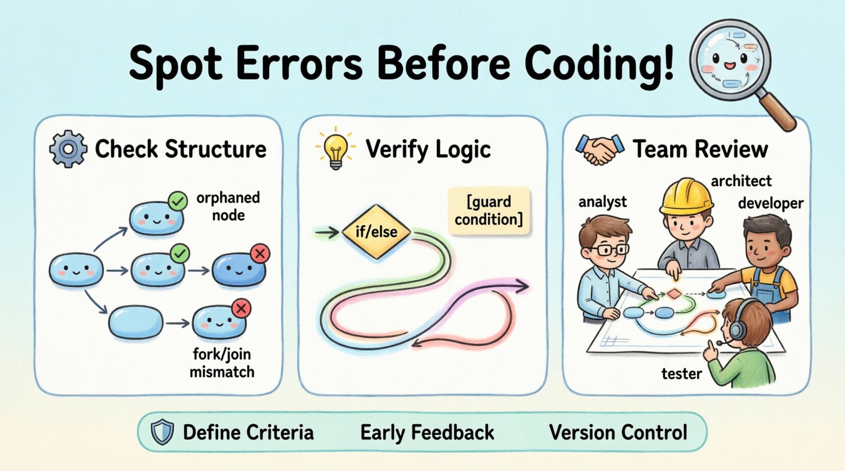
1. Orphaned Nodes
An orphaned node is an activity that has no incoming or outgoing connections. In a valid diagram, every activity must be reachable from the initial node and must eventually lead to the final node (unless it is an infinite loop scenario, which must be explicitly marked). If a node is disconnected, the flow stops abruptly, or the logic becomes unreachable.
2. Unresolved Forks and Joins
Fork nodes split the control flow into parallel threads. Join nodes merge these threads back together. A common error occurs when a fork creates parallel paths that never converge. This results in a dangling thread. Conversely, a join node without a corresponding fork can cause synchronization errors where the system waits for a thread that never arrives.
3. Missing Decision Nodes
Decision nodes represent conditional logic (e.g., if/else). Every decision node must have at least two outgoing edges. A decision node with only one outgoing edge implies that the condition does not matter, which is usually a modeling error. Each path leaving a decision must be labeled with a guard condition.
4. Infinite Loops Without Exit
While loops are valid, they must have a defined exit condition. If a cycle in the activity diagram does not have a guard condition that evaluates to false, the process will never terminate. In a software system, this translates to an infinite loop bug.
🔄 Control Flow and Logic Checks
Once the structure is sound, the focus shifts to the logic. This involves tracing the paths to ensure the business rules are correctly implemented.
Path Coverage
Every possible path from the start node to the end node should be traceable. This includes both the happy path (successful execution) and the exception paths (errors, cancellations, timeouts). A robust diagram accounts for what happens when a user cancels a transaction or when a service times out.
Guard Conditions
Guard conditions are the Boolean expressions that determine which branch of a decision node is taken. Validation requires checking that these conditions are mutually exclusive and collectively exhaustive. If two conditions overlap, the flow becomes ambiguous. If they do not cover all possibilities, the system may hang or crash.
State Consistency
Activities often change the state of an object. For example, an activity might change an order status from Placed to Shipped. Validation involves checking that the activity can only be executed if the object is in the correct state. If the diagram allows an activity to run on an invalid state, the resulting code will likely throw exceptions.
📊 Object Flow and Resource Constraints
Activity diagrams are not just about control; they are also about data. Object flows show how data moves between activities. Validating this flow ensures that the right information is available at the right time.
Data Availability
Every activity requires specific inputs. Validation checks if the input data is produced by a preceding activity. If an activity expects a user ID, but the previous step only passes a session token, there is a mismatch. This data gap must be resolved in the design phase.
Resource Constraints
Some activities require exclusive access to a resource, such as a database connection or a hardware device. The diagram should reflect whether these resources are locked or shared. If multiple parallel threads try to access the same resource without synchronization, race conditions will occur.
Table: Common Object Flow Errors
| Error Type | Symptom | Impact |
|---|---|---|
| Missing Input | Activity runs without required data | Null pointer exceptions |
| Unconsumed Output | Data generated but never used | Memory leaks |
| Type Mismatch | String passed where number expected | Runtime parsing errors |
| Race Condition | Two threads write to same object | Data corruption |
⚙️ Validation Techniques & Methods
How do you actually perform these checks? There are several established methods that rely on human insight rather than automated tools.
1. The Walkthrough Method
A walkthrough involves a group of stakeholders walking through the diagram step-by-step. One person acts as the moderator, tracing a path while others observe. This method is effective for catching logical gaps that a single designer might miss. It encourages discussion about edge cases and business rules.
2. Peer Review
Passing the diagram to a colleague who was not involved in the initial design is a powerful validation technique. Fresh eyes can spot assumptions that the original designer took for granted. The reviewer should focus on clarity and completeness rather than syntax.
3. Use Case Mapping
Every activity should map back to a specific use case or requirement. Validation involves creating a traceability matrix. For every activity node, there must be a corresponding requirement ID. If an activity has no requirement, it might be unnecessary scope creep. If a requirement has no activity, it is incomplete.
4. Simulation and Tracing
For critical paths, it is helpful to simulate the execution. Imagine a specific user story and trace the data through the diagram. Ask: “If I click this button, what happens next?” Then ask: “What if the network fails here?” This mental simulation helps identify missing error handling paths.
🤝 Collaborative Review Strategies
Validation is rarely a solitary task. Involving different perspectives ensures that the diagram meets technical, business, and user needs.
- Business Analysts: Validate that the logic matches the business rules. They ensure the diagram reflects the actual workflow, not an idealized version.
- System Architects: Validate the technical feasibility. They check if the proposed flow aligns with system constraints, security policies, and integration points.
- Developers: Validate the implementation details. They identify if the diagram is too abstract to be coded or if it contains logic that is too complex to maintain.
- QA Engineers: Validate testability. They look for clear decision points and error states that can be easily tested.
🛠️ Integrating Validation into Your Workflow
To make validation effective, it must be integrated into the development lifecycle. It should not be an afterthought.
1. Define Validation Criteria
Establish a checklist of what constitutes a “valid” diagram. This includes rules like “All decision nodes must have labels” and “All parallel paths must join.” Having clear criteria removes ambiguity during reviews.
2. Early Feedback Loops
Do not wait until the diagram is finished to validate it. Validate incrementally. As you add a new section of the workflow, check it against the existing structure. This prevents the need to refactor the entire diagram later.
3. Version Control
Just like code, diagrams should be versioned. Changes to the diagram should be documented. If a change invalidates a previous validation, the new version must be re-validated. This ensures that the diagram remains accurate as requirements evolve.
🚦 Handling Concurrency and Parallelism
Activity diagrams are particularly useful for modeling concurrent processes. However, concurrency introduces complexity that requires careful validation.
Synchronization Barriers
When parallel threads must wait for each other, synchronization barriers are used. Validation must ensure that these barriers are not too restrictive. If the wait time is too long, the system performance degrades. If the wait time is too short, the system might proceed with incomplete data.
Deadlock Prevention
A deadlock occurs when two or more threads are waiting for each other to release resources. In a diagram, this looks like a circular dependency between parallel flows. Validation involves checking for circular waits. If flow A waits for B, and B waits for A, the system will freeze.
Thread Safety
Parallel activities often access shared data. Validation must confirm that the diagram accounts for thread safety. If two activities modify the same object simultaneously, the diagram should indicate locking mechanisms or immutable data structures.
📝 Documenting Findings & Changes
Validation is only useful if the findings are actionable. Documenting the results of the validation process is crucial for knowledge transfer and accountability.
1. Error Logs
Maintain a log of all errors found during validation. Include the node ID, the type of error, the severity, and the proposed fix. This log serves as a quality metric for the design phase.
2. Change Requests
If validation reveals a fundamental flaw in the requirement, a change request should be initiated. Do not force the diagram to fit a flawed requirement. It is better to update the requirement than to build a broken system.
3. Approval Sign-off
Once validation is complete and all critical errors are resolved, a formal sign-off should be obtained. This approval indicates that the design is ready for development. It shifts the responsibility from the design team to the development team.
🔎 Deep Dive: Specific Validation Scenarios
To further illustrate the importance of validation, let us look at specific scenarios where errors commonly occur.
Scenario A: Cancellation Flows
Users often need to cancel processes. A common error is modeling the cancellation only at the beginning of the flow. Validation requires checking if cancellation is possible at intermediate steps. For example, can a user cancel an order after it has been shipped? The diagram should explicitly show this path.
Scenario B: Timeouts and Retries
Network calls often fail. A robust diagram includes retry logic. Validation checks if the retry limit is defined. If a retry loop has no exit condition, the system might retry indefinitely, consuming resources.
Scenario C: Exception Handling
What happens when an activity fails? The diagram should show an exception handler. Validation ensures that exceptions do not leave the system in an inconsistent state. For instance, if a payment fails, the inventory reservation should be released.
📈 Measuring Validation Effectiveness
How do you know if your validation process is working? You can track several metrics.
- Defect Density: The number of errors found in the diagram per size of the diagram. A high density suggests a need for better guidelines.
- Rework Rate: The amount of code changed after development due to design errors. A low rate indicates effective validation.
- Review Time: The time spent reviewing diagrams. If this increases over time, the complexity of the designs may be growing too fast.
🛡️ Security and Compliance Considerations
Validation is not just about logic; it is also about security and compliance. The diagram must reflect security policies.
Authentication Points
Every sensitive activity should have an authentication guard. Validation checks if the diagram ensures users are logged in before accessing specific functions.
Data Privacy
If the activity diagram involves personal data, it must show how that data is handled. Validation ensures that data is not passed to unauthorized components or stored insecurely.
Audit Trails
For compliance, certain activities must be logged. The diagram should indicate where logging occurs. Validation ensures that no critical action is performed without a record.
🌟 Final Thoughts on Design Quality
Activity diagram validation is a discipline that separates good systems from great ones. It requires patience, attention to detail, and a willingness to challenge assumptions. By applying the techniques outlined in this guide, teams can ensure that their designs are robust, logical, and ready for implementation.
Remember that a diagram is a communication tool. If it is flawed, the communication is flawed. Validation bridges the gap between abstract requirements and concrete code. It protects the team from the high costs of fixing errors late in the lifecycle. Embrace validation as a core part of the design process, and the quality of your software will naturally improve.
Start today. Review your current diagrams. Look for orphaned nodes, check your decision logic, and verify your data flows. The effort invested now will pay dividends throughout the entire development cycle.