When designing complex systems, activity diagrams serve as the backbone for visualizing workflows and control flows. However, even the most meticulously crafted diagrams can encounter logical bottlenecks. You might find yourself staring at a process that never reaches its final state, or a decision node that seems to ignore valid inputs. This phenomenon, often referred to as state logic getting stuck, requires a methodical approach to diagnose and resolve. This guide provides a deep dive into identifying, analyzing, and fixing common pitfalls in activity diagram modeling.
Whether you are mapping out business processes or defining software state transitions, the integrity of your control flow is paramount. A stuck state implies a deadlock, an infinite loop, or an unreachable destination. Below, we break down the technical reasons why this happens and provide actionable steps to restore the flow of your diagrams.
Understanding the Mechanics of Flow Stalls 🔍
Before troubleshooting, it is essential to understand what constitutes a “stuck” state. In the context of activity diagrams, a flow stall occurs when the execution token cannot progress from one node to the next according to the defined semantics. This is not merely a visual error; it is a logical contradiction within the model.
Activity diagrams rely on two primary types of flows:
- Control Flow: Represents the sequence of activities. It dictates the order in which actions occur.
- Object Flow: Represents the movement of data or objects between activities. It ensures that necessary inputs are available before an action starts.
When logic gets stuck, it is usually because the control flow cannot transition, or the object flow lacks the required data. Troubleshooting involves tracing these tokens through the diagram to find where they halt.
Common Triggers for Logic Deadlocks 🚫
Identifying the root cause is faster than guessing. Below is a table outlining common symptoms and their corresponding technical causes. This structure helps you quickly narrow down the problem area.
| Symptom | Likely Cause | Impact |
|---|---|---|
| Process halts at a decision node | Missing or contradictory guard conditions | Deadlock or incomplete path |
| Activity never completes | Infinite loop without exit condition | Resource exhaustion |
| Unreachable final node | Disconnected branches or orphaned nodes | Incomplete process representation |
| Concurrency mismatch | Missing join node after fork | Lost tokens or race conditions |
Missing Guard Conditions
Decision nodes act as traffic lights in your workflow. They require a guard condition (a boolean expression) to determine which outgoing edge to take. If a decision node has multiple outgoing edges but no guard conditions are assigned, the behavior is undefined. The modeler might assume a default path, but the specification does not guarantee one.
To fix this:
- Ensure every outgoing edge from a decision node has a distinct guard condition.
- Verify that the conditions are mutually exclusive where appropriate.
- Check that at least one condition is always true to prevent the flow from stopping.
Infinite Loops and Missing Exit Conditions
Loops are necessary for iterations, but they must be bounded. A common error is creating a loop where the condition to exit never becomes false. This often happens when the activity inside the loop does not modify the state required to satisfy the exit condition.
For example, if an activity “Update Status” is supposed to change a status from “Pending” to “Complete”, but the update action is flawed or missing, the loop will persist indefinitely. Always verify that the feedback loop modifies the relevant state variable.
Diagnosing Control Flow Issues 🧩
Control flow is the most common area where logic gets stuck. It dictates the sequence. When tracing the flow, imagine a token moving from the initial node to the final node.
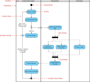
Initial and Final Node Confusion
Every activity diagram must have exactly one initial node and at least one final node. If the diagram has multiple initial nodes, the entry point is ambiguous. If there is no path from the initial node to a final node, the logic is incomplete.
- Check Entry Points: Ensure the initial node (filled circle) is connected to a valid action.
- Check Exit Points: Ensure all logical paths eventually lead to an activity final node (filled circle within a larger circle) or a flow final node (filled circle within a cross).
Fork and Join Synchronization
Fork nodes split the flow into concurrent threads. Join nodes merge them back together. A frequent source of stuck logic is a mismatch between forks and joins.
- Synchronization: A join node waits for all incoming edges from a fork to be completed before proceeding. If one branch is stuck, the join waits forever.
- Orphaned Forks: If a fork has outgoing edges that never reach a join, the threads run off into infinity without synchronizing.
Debugging Step: Trace every fork. Does every parallel path eventually merge? If not, you have an orphaned thread that might be consuming resources or hanging indefinitely.
Resolving Object Flow Conflicts 📦
While control flow moves the process, object flow moves the data. Stuck logic often occurs because an action cannot execute because it lacks the necessary input object.
Data Dependency Chains
If Action B requires the output of Action A, and Action A is stuck, Action B cannot start. This is a cascading failure. You must verify the data flow consistency.
- Verify Object Creation: Ensure the object is created before it is consumed. Look for the initial object node.
- Check Object Types: Ensure the output of Action A matches the input type required by Action B.
- Review Multiplicity: If Action A produces a list of objects, ensure Action B can handle a list, not a single item.
Read-Write Conflicts
In concurrent flows, multiple actions might try to modify the same object simultaneously. This can lead to race conditions where the state becomes unpredictable, effectively “sticking” the logic in an invalid state. Use read-write markers or ensure proper locking mechanisms in the underlying system design.
Managing Swimlanes and Partition Errors 🏊
Swimlanes organize activities by responsibility, such as roles or system components. When logic gets stuck across swimlanes, it often involves communication gaps.
Inter-Swimlane Communication
Control flows crossing swimlane boundaries can be tricky. The flow must explicitly cross the boundary. Sometimes, a connector is placed visually within a lane but technically belongs to another.
- Boundary Checks: Ensure every edge crossing a swimlane boundary is explicitly drawn across the line.
- Responsibility Verification: Confirm that the action receiving the input belongs to the correct swimlane. An action in the “Customer” lane cannot directly receive control from the “Server” lane without a defined interface or transition.
Local vs. Global Flow
Some modeling tools allow for nested activity diagrams. An action inside a sub-activity diagram might appear connected to the outside, but it is actually local. Ensure that external flows connect to the correct entry and exit points of the sub-activity.
Validation Checklist for Complex Workflows ✅
Before finalizing your diagram, run through this validation checklist. It covers the most frequent causes of stuck state logic.
- Initial Node: Is there exactly one initial node?
- Final Nodes: Is every possible path reachable from a final node?
- Decision Nodes: Do all outgoing edges have guard conditions?
- Loops: Are all loops guaranteed to terminate? Is there an exit condition?
- Fork/Join: Does every fork have a corresponding join?
- Object Flow: Is every object consumed after it is produced?
- Swimlanes: Do all boundary crossings represent valid handoffs?
- Edge Labels: Are all edges labeled clearly to avoid ambiguity?
Preventing Future Logic Stalls 🛡️
Once you have fixed the current diagram, take steps to prevent recurrence. Consistency in modeling standards reduces ambiguity.
Standardize Naming Conventions
Use clear, descriptive names for nodes and edges. Instead of “Node A” and “Node B”, use “Validate Input” and “Process Payment”. This reduces the cognitive load when tracing the flow mentally.
Regular Peer Reviews
A fresh pair of eyes can spot a disconnected edge or a missing guard condition that you might overlook. Establish a review process where another architect traces the flow from start to finish.
Use Automated Validation Tools
Many modeling environments offer syntax checking. Enable these features to catch basic structural errors, such as unconnected nodes or missing labels, before you begin deep logical analysis.
Document Assumptions
If the diagram relies on external systems or specific timing constraints, document these assumptions. A logic stall might be caused by an external dependency that was assumed to be available but is not.
Advanced Scenarios: Time and Concurrency ⏱️
In high-fidelity activity diagrams, time and concurrency play a significant role. Ignoring these can lead to subtle logic traps.
Timeout Mechanisms
What happens if an activity takes too long? A robust diagram includes a timeout mechanism. If an action exceeds a specified duration, the flow should divert to an error handling path rather than hanging indefinitely.
- Signal Events: Use signal events to represent asynchronous notifications that might break a wait.
- Time Guards: If supported, apply time constraints to decision nodes to force a path selection.
Deadlock Detection
Deadlocks occur when two or more threads wait for each other to release resources. In activity diagrams, this looks like two concurrent branches waiting for a join, where each branch is waiting for the other to complete an action.
- Resource Ordering: Ensure that concurrent branches acquire resources in a consistent order.
- Asynchronous Actions: Where possible, use asynchronous actions to decouple dependencies.
Summary of Diagnostic Steps 📝
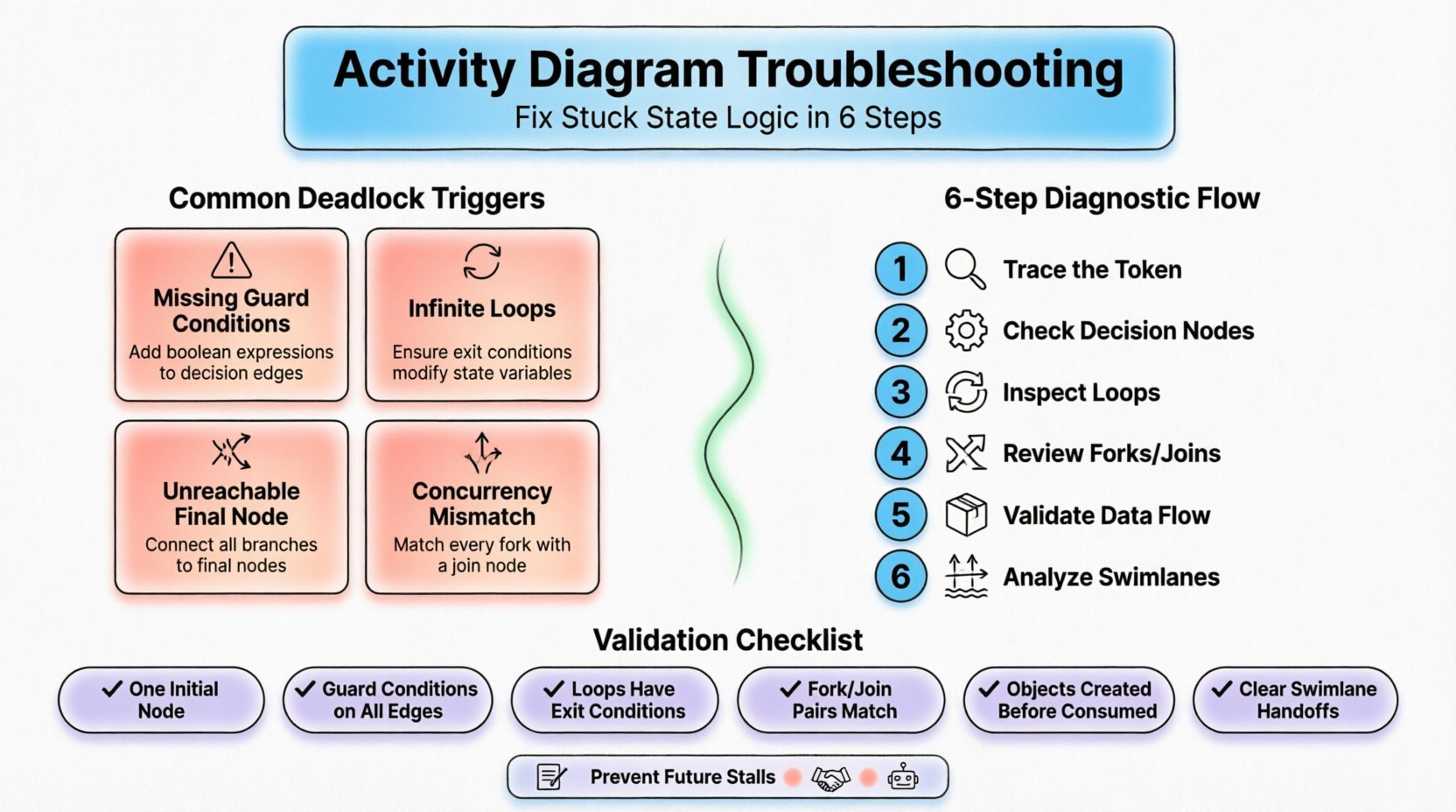
To recap, when your activity diagram state logic gets stuck, follow this sequence:
- Trace the Token: Manually move a token through the diagram to find the halt point.
- Check Decision Nodes: Verify guard conditions and completeness.
- Inspect Loops: Confirm termination conditions exist.
- Review Forks and Joins: Ensure synchronization is correct.
- Validate Data Flow: Check that objects are created and consumed correctly.
- Analyze Swimlanes: Ensure handoffs are valid.
By applying these rigorous checks, you can transform a broken model into a reliable blueprint for system behavior. The goal is not just to draw a diagram, but to ensure the logic it represents is executable and sound.