Software development relies heavily on clear communication. When stakeholders provide text-based requirements, ambiguity often creeps in. A sentence written by a product manager might be interpreted differently by a developer or a tester. This is where Unified Modeling Language (UML) becomes essential. Specifically, the Use Case Diagram offers a visual bridge between natural language and system behavior.
Translating textual requirements into UML use cases is not just about drawing boxes and lines. It is a rigorous process of analysis, decomposition, and validation. This guide explores the methodology of converting raw text into structured diagrams that accurately represent system functionality. We will cover actor identification, boundary definition, and relationship modeling without relying on proprietary tools.
🧱 Understanding the Foundation: Requirements vs. Use Cases
Before drawing a single line, one must distinguish between a requirement and a use case. While they are related, they serve different purposes in the system design process.
- Requirements: These are statements of what the system must do. They are often written in natural language (e.g., “The system shall allow users to reset their password”).
- Use Cases: These describe a sequence of actions that the system performs to yield an observable result of value to an actor. A use case is a functional unit of behavior.
The translation process involves abstracting specific requirements into a cohesive scenario. One requirement might contribute to a single use case, or multiple requirements might define the steps within one complex use case.
🔍 Key Distinctions
Confusion often arises when teams treat every requirement as a separate use case. This leads to bloated diagrams with hundreds of disconnected boxes. Instead, group related functionalities into logical goals.
- Requirement: “The system must validate the email format.”
- This is a constraint or a rule.
- Use Case: “Register New Account.”
- This includes validation as a step within the goal.
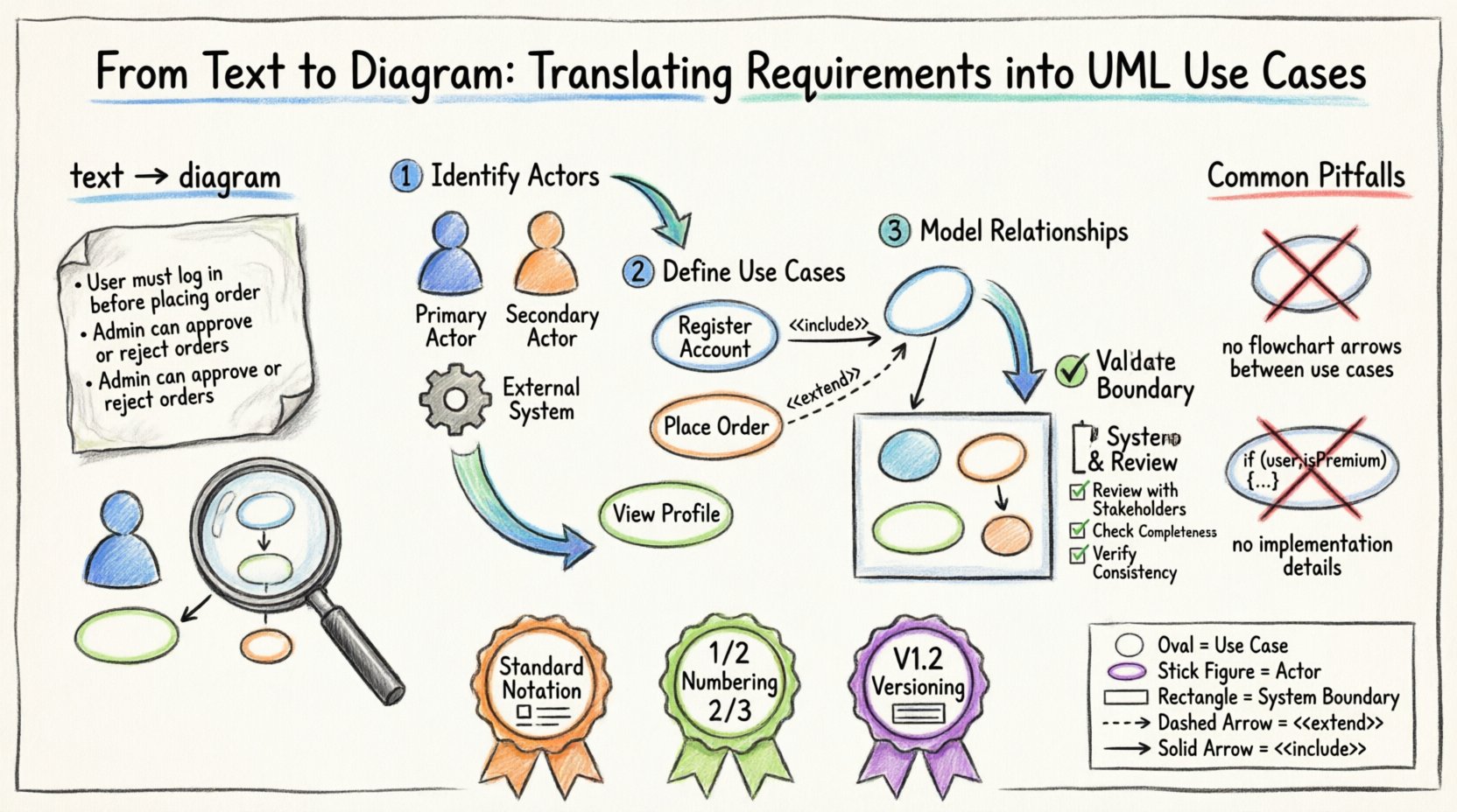
👥 Step 1: Identifying Actors
The first visual element in any use case diagram is the actor. An actor represents a role played by an entity that interacts with the system. It is crucial to remember that actors are not necessarily people; they can be external systems, hardware, or organizations.
📋 Types of Actors
| Type | Description | Example |
|---|---|---|
| Primary Actor | Initiates the use case to achieve a goal. | Customer starting a purchase. |
| Secondary Actor | Provides input or receives output but does not initiate the flow. | Payment Gateway validating a transaction. |
| External System | An automated system that interacts with your software. | Inventory Management API. |
🚀 How to Extract Actors from Text
Read through the requirement documents and highlight nouns that represent roles. Look for phrases like “The user,” “The admin,” “The third-party service,” or “The mobile device.” Filter out specific job titles unless the system behaves differently based on those titles (which would suggest a different actor).
- Bad: “John the Manager” and “Sarah the Manager” are two actors.
- Good: “Manager” is the actor. Permissions differ, but the interaction pattern is the same.
🎯 Step 2: Defining Use Cases
Once actors are identified, map the goals they wish to achieve. A use case should always be named with a verb-noun structure (e.g., “Submit Order,” not “Order Submission”).
📝 Crafting the Use Case Description
Even if you are creating a diagram, text descriptions accompany the visual elements. A robust use case description includes:
- Preconditions: What must be true before the use case starts? (e.g., User is logged in).
- Main Flow: The primary path to success. Step-by-step interactions.
- Alternative Flows: Variations that deviate from the main path (e.g., invalid input).
- Postconditions: The state of the system after completion.
🧩 Decomposing Complex Goals
If a requirement describes a massive workflow, break it down. A “Manage Inventory” goal might be too broad for a single box. Decompose it into:
- Add Item
- Update Stock Levels
- View Inventory Report
This keeps the diagram readable and the requirements traceable.
🔗 Step 3: Modeling Relationships
Relationships define how use cases and actors interact. Using the correct relationship type prevents misinterpretation of system logic. There are three primary relationship types in UML use cases.
1. Association
A simple line connecting an actor to a use case. It indicates that the actor can initiate or participate in that specific use case.
- Rule: Only draw a line if the actor directly triggers the use case.
- Note: Do not draw lines between use cases (unless using Include/Extend).
2. Include
The <<include>> relationship indicates that one use case must always incorporate the behavior of another. It is a mandatory dependency.
- Use Case A includes Use Case B means B is always executed when A runs.
- Example: "Place Order" includes "Validate Payment".
Think of this as a subroutine call. You cannot do the main task without the included task.
3. Extend
The <<extend>> relationship indicates optional behavior that adds to the base use case under specific conditions.
- Use Case B extends Use Case A means B only happens if a condition is met.
- Example: "Apply Discount" extends "Place Order".
This keeps the main flow clean by moving exception or optional logic to separate boxes.
4. Generalization
This is the inheritance relationship. A specialized actor or use case can inherit the behavior of a general one.
- Actor Generalization: "Senior Manager" is a type of "Manager".
- Use Case Generalization: "Pay with Credit Card" is a type of "Pay".
📦 Step 4: Defining System Boundaries
Every use case diagram must clearly define what is inside the system and what is outside. This is represented by a rectangle enclosing all use cases.
🛡️ Why Boundaries Matter
- Scope Control: Prevents scope creep by showing exactly what the current system version handles.
- Clarity: Makes it obvious which actors are external and which use cases are internal.
🧭 Determining the Edge
Ask yourself: "Does this functionality happen within the software, or is it handled by the user/environment?"
- If the system calculates a tax rate, it is inside the boundary.
- If the user enters the tax code, the entry is inside, but the tax code logic might be external.
- If the system sends an email, the sending mechanism is inside, but the email server is outside.
📊 Step 5: Validation and Review
Once the diagram is drafted, it must be validated against the original text requirements. This step ensures accuracy and completeness.
✅ Checklist for Verification
- Completeness: Are all primary requirements represented by at least one use case?
- Consistency: Do the actor names match the terminology in the requirements document?
- Traceability: Can you trace every line in the diagram back to a requirement ID?
- Clarity: Is the diagram readable? Are lines crossing unnecessarily?
🔄 Iterative Refinement
Requirements change. As they do, the diagram must evolve. Do not treat the diagram as a static artifact. It is a living document that grows with the project. Schedule regular reviews where stakeholders walk through the diagram alongside the text requirements.
⚠️ Common Pitfalls to Avoid
Even experienced analysts make mistakes during the translation process. Being aware of common errors helps maintain diagram quality.
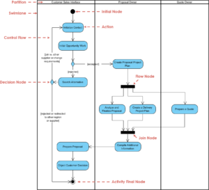
🚫 The "Process Flow" Mistake
A common error is drawing sequence flow (arrows going from one box to another in a sequence) within a use case diagram. Use case diagrams are not flowcharts. They show who does what, not how the steps happen sequentially inside the box.
- Incorrect: Drawing arrows between "Login" and "Search".
- Correct: Show "Login" and "Search" as separate use cases connected to the "User" actor.
🚫 Over-Specification
Do not include implementation details. If a requirement says "The system shall store the password in a database," do not draw a use case for "Store in Database." That is an internal mechanism, not a user goal.
🚫 Ambiguous Actors
Avoid actors like "System" or "Computer." These are too vague. Replace them with the specific role, such as "Backend Service" or "Hardware Controller." If the actor is the system itself, it is usually not an actor in the diagram context, but rather the boundary.
🛠️ Best Practices for Documentation
To ensure the diagrams remain useful throughout the project lifecycle, follow these documentation practices.
- Use Standard Notation: Stick to UML standards for icons and lines. Avoid custom shapes unless absolutely necessary.
- Numbering: Assign unique IDs to use cases (e.g., UC-001) for easy referencing in test cases.
- Versioning: Keep track of diagram versions. When a requirement changes, update the diagram and note the version number.
- Legend: If you use non-standard icons, provide a legend. If you use standard UML, a legend is usually not required.
📈 Impact on Development and Testing
The effort put into translating requirements into UML use cases pays dividends in the later stages of development.
🧪 Test Case Generation
Each use case naturally suggests test scenarios. The main flow becomes the "Happy Path" test. Alternative flows become negative tests or edge-case tests. This alignment reduces the gap between design and quality assurance.
👷 Developer Clarity
Developers often struggle with textual requirements that lack context. A visual diagram provides the context of interaction. It clarifies who starts the process and what the system expects in return.
🎨 Visual Structure Example
Consider a simple requirement: "The user must be able to view their profile and update their contact information."
Translation steps:
- Identify Actor: User.
- Identify Goals: View Profile, Update Contact Info.
- Define Boundary: User Management System.
- Draw Association: Line from User to View Profile.
- Draw Association: Line from User to Update Contact Info.
This simple structure ensures that the requirements are captured without unnecessary complexity.
📝 Summary of Translation Workflow
To summarize the process, follow this logical sequence:
- Review: Read all textual requirements thoroughly.
- Extract: Highlight actors and functional goals.
- Define: Write descriptions for preconditions and flows.
- Relate: Connect actors to use cases and use cases to each other.
- Validate: Check against requirements for gaps.
By adhering to this structured approach, teams ensure that the visual representation remains faithful to the textual intent. This alignment is critical for building software that meets actual user needs.
The transition from text to diagram is a skill that improves with practice. It requires patience to decompose complex requirements and discipline to ignore implementation details. When done correctly, the UML use case diagram becomes a central artifact that guides design, development, and testing.
Focus on the what and the who. Leave the how for later design phases. This separation of concerns keeps the use case diagram clean and effective. As the project evolves, refer back to these diagrams to ensure that new features do not contradict existing definitions. This consistency builds trust between stakeholders and the development team.