Communication diagrams serve as a critical tool for visualizing the dynamic behavior of a system. While many practitioners stop at drawing simple object connections, true modeling power lies in understanding the nuances of interaction flows. This guide explores the deeper mechanics of these diagrams, focusing on semantic precision and structural clarity. We will move past the elementary definitions to examine how these diagrams capture complex system logic without relying on proprietary tools or marketing fluff.
Understanding the Foundation 🔍
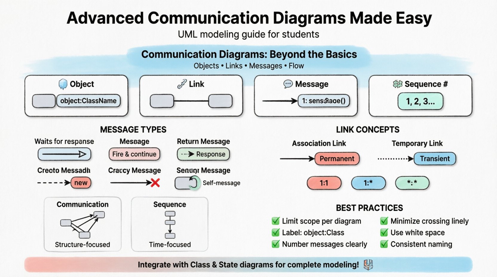
Before diving into advanced techniques, it is necessary to establish a shared understanding of the core components. A communication diagram, often referred to as a collaboration diagram in older UML specifications, focuses on the organization of objects and the messages they exchange. Unlike sequence diagrams, which prioritize time ordering vertically, communication diagrams emphasize the structural relationships between objects.
- Objects: Instances of classes that participate in the interaction.
- Links: The connections that allow objects to communicate with one another.
- Messages: The signals sent from one object to another to trigger behavior.
- Sequence Numbers: Labels that indicate the order of message execution.
Mastering these basics is the prerequisite for advanced modeling. However, simply drawing boxes and arrows is insufficient for capturing real-world complexity. The advanced practitioner must understand the semantics behind every line drawn.
Deep Dive into Object Links 🔗
Links in a communication diagram represent navigational paths. They are not merely decorative; they define the actual capability of an object to reach another. In advanced modeling, the absence of a link implies that communication cannot occur directly between those specific instances.
Types of Links
- Association Links: Represent structural relationships defined in the class diagram. These exist regardless of whether an interaction is currently happening.
- Temporary Links: Created dynamically during the execution of a specific scenario. These are often used to represent messages that traverse paths not permanently established in the system architecture.
When modeling complex systems, you must decide whether to draw a permanent link or a temporary one. Permanent links suggest a stable architectural dependency. Temporary links suggest a transient relationship, such as a message sent to a third-party service that does not maintain a persistent connection.
Link Multiplicity
Just as classes have multiplicity constraints (e.g., 1 to many), links can also carry this information. This is crucial for understanding how many instances can interact.
- One-to-One: A single instance interacts with a single instance of another class.
- One-to-Many: One instance may communicate with multiple instances of another class.
- Many-to-Many: Multiple instances on both sides can interact.
Ignoring multiplicity can lead to ambiguity in the requirements. If a user can interact with multiple orders simultaneously, the link must reflect that capacity.
Understanding Message Semantics 💬
The arrow used to represent a message carries significant meaning. In advanced diagrams, the arrow type indicates the nature of the interaction. This affects how developers interpret the code implementation.
Message Types
| Arrow Type | Visual Representation | Meaning |
|---|---|---|
| Synchronous | Filled Arrowhead | The sender waits for the receiver to complete the operation before continuing. |
| Asynchronous | Open Arrowhead | The sender fires the message and continues immediately without waiting. |
| Return | Dashed Open Arrowhead | Indicates a return value or response from the receiver. |
| Create | Dashed Arrow with ⇨ | Indicates the creation of a new object instance. |
| Destroy | Open Arrow with ⇨ | Indicates the termination of an object instance. |
Self-Message
Objects often call methods on themselves. In a communication diagram, this is drawn as a loop starting and ending on the same object. This is common for recursive operations or internal state changes triggered by external input.
- Use self-messages to clarify complex internal logic.
- Keep self-messages simple to avoid cluttering the diagram.
- Indicate the method name clearly within the loop.
Handling Complexity with Multiplicity ⚖️
Real-world systems rarely involve single instances. They involve collections of objects. Communication diagrams can become messy when representing many-to-many interactions. To maintain clarity, advanced modeling techniques focus on scope and iteration.
Iterative Messages
When an object sends a message to a collection of objects, it is often represented as an iteration. Instead of drawing a separate arrow for every instance, use a notation to indicate repetition.
- For-Each Loop: Indicate that a message is sent to every instance in a collection.
- Range Notation: Specify a range of instances if applicable.
This approach keeps the diagram readable while conveying the logic that applies to multiple entities. It prevents the visual noise of drawing dozens of identical arrows.
Timing and Constraints ⏱️
While sequence diagrams are better at showing precise timing, communication diagrams can still incorporate temporal constraints. These constraints add a layer of realism to the model.
- Time Constraints: Specify that a message must be received within a certain duration (e.g., 500ms).
- Event Constraints: Specify that a message must be received after a specific event occurs.
When adding these constraints, place them near the message arrow. Use brackets to enclose the constraint text. This ensures that the reader knows exactly what conditions must be met for the interaction to proceed.
Communication vs Sequence Diagrams 🆚
Choosing between a communication diagram and a sequence diagram is a common decision point. Both represent the same information but with different emphases. Understanding when to use which is key to effective documentation.
| Feature | Communication Diagram | Sequence Diagram |
|---|---|---|
| Primary Focus | Structural relationships | Time ordering |
| Layout | Organized by object connections | Organized by vertical timeline |
| Readability | Better for showing object topology | Better for showing complex message flows |
| Complexity | Can get tangled with many links | Can get long and vertical |
| Use Case | High-level architectural overview | Detailed interaction logic |
Use communication diagrams when you want stakeholders to understand how objects relate to one another. Use sequence diagrams when the exact order of events is the critical factor.
Best Practices for Clear Modeling ✅
Creating a diagram is not just about drawing; it is about communication. The goal is to convey information efficiently to developers, testers, and stakeholders. Follow these guidelines to ensure your diagrams remain effective.
- Limit Scope: Do not try to model the entire system in one diagram. Break interactions down into specific scenarios.
- Label Objects Clearly: Use the format objectName:ClassName to distinguish instances from classes.
- Number Messages: Always include sequence numbers to remove ambiguity about execution order.
- Minimize Crossing Lines: Arrange objects to minimize the number of crossing links. This improves visual scanning.
- Use White Space: Leave space between objects to allow for message arrows. Crowded diagrams are hard to read.
- Consistent Naming: Use consistent naming conventions for objects and methods across all diagrams.
Integrating with Other UML Views 🔗
Communication diagrams do not exist in isolation. They are part of a larger ecosystem of models. To gain a complete picture of the system, you must integrate communication diagrams with class diagrams and state machine diagrams.
Alignment with Class Diagrams
Ensure that the objects in your communication diagram exist in your class diagram. Every object instance must correspond to a defined class. If an object appears in an interaction but has no class definition, the system is incomplete.
- Verify that all links in the communication diagram correspond to associations in the class diagram.
- Check that the attributes accessed via messages are defined in the class structure.
Alignment with State Machine Diagrams
Messages often trigger state transitions. The communication diagram should reflect the states that allow a message to be processed. If an object is in a state where it cannot receive a specific message, the interaction is invalid.
- Map the messages in the communication diagram to the events in the state diagram.
- Ensure that the target states match the expected behavior after the message is processed.
Common Pitfalls to Avoid ⚠️
Even experienced modelers can fall into traps that reduce the value of their diagrams. Being aware of these common issues helps maintain high standards.
- Overloading Messages: Do not put too much information on a single arrow. Keep the label focused on the action.
- Ignoring Return Messages: While optional, return messages clarify data flow. Omitting them can obscure error handling logic.
- Complex Nesting: Avoid nested interactions unless absolutely necessary. Flatten the diagram where possible.
- Inconsistent Notation: Do not mix different arrow styles or labeling conventions in the same diagram.
- Missing Context: Ensure the diagram explains the purpose of the interaction. A title or brief description helps.
Future Considerations in Modeling 🚀
As systems evolve, so do the requirements for modeling. Modern architectures, such as microservices and event-driven systems, introduce new challenges for traditional diagrams.
- Distributed Systems: Links may cross network boundaries. Clearly indicate which objects are local and which are remote.
- Event-Driven Flows: Messages may be asynchronous by default. Ensure the arrow types reflect this architectural pattern.
- Scalability: Consider how the diagram changes when the number of instances scales. Use iteration notation to handle growth.
By keeping these factors in mind, you can create diagrams that remain relevant as the system matures. The goal is to create a living documentation that supports development and testing without becoming obsolete.
Final Thoughts on Diagrammatic Precision 📝
Advanced communication diagrams require a balance of technical accuracy and visual clarity. They are not just drawings; they are specifications of behavior. When executed correctly, they reduce ambiguity in requirements and provide a clear path for implementation.
Focusing on the semantics of links, messages, and objects ensures that the diagram conveys the necessary logic. Avoiding common pitfalls and integrating with other views creates a cohesive model of the system. This approach leads to better software outcomes and clearer team communication.