Understanding how software behaves over time is critical for building robust systems. While structure diagrams show what a system consists of, behavioral diagrams explain how it acts. Among these, the UML state machine diagram stands out as a specialized tool for modeling the dynamic behavior of individual objects. This guide provides a deep dive into modeling state changes, focusing on the mechanics, symbols, and logical flow required to create accurate representations of system behavior.
Whether you are designing a payment gateway, a traffic control system, or a complex user authentication flow, defining the lifecycle of an entity is essential. This tutorial covers the core components, construction steps, and advanced techniques without relying on specific proprietary tools. We will focus on the universal standards defined by the Object Management Group (OMG).
What is a UML State Machine Diagram? 🧠
A UML state machine diagram, often referred to as a statechart diagram, describes the behavior of a single object in response to a series of events. It is not a flowchart. Flowcharts represent procedural logic, whereas state diagrams represent the history and context of an object.
- Focus: It tracks the state of an object throughout its lifecycle.
- Trigger: Transitions occur based on specific events.
- Constraint: Guards determine if a transition is allowed.
- Action: Activities may occur upon entering, exiting, or during a transition.
This distinction is vital. A state machine does not just show a path from A to B; it shows that the object must be in state A before it can move to state B. It captures the memory of the system.
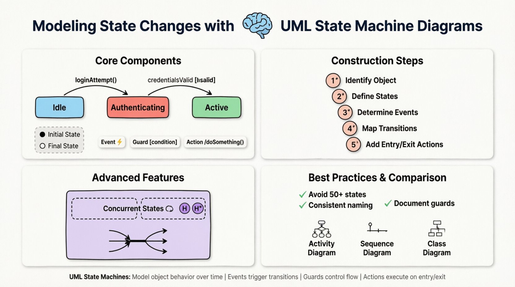
Core Components of a State Machine 🧩
To model state changes effectively, you must understand the atomic elements that make up the diagram. Each element serves a specific semantic purpose in the modeling environment.
1. States 🏷️
A state represents a condition or situation during the life of an object in which it satisfies some condition, performs some activity, or waits for some event. States are typically drawn as rounded rectangles.
- Simple State: Contains no sub-states. It is an atomic unit of behavior.
- Composite State: Contains a hierarchy of sub-states. This is used to manage complexity by grouping related behaviors.
- Shallow vs. Deep History: Composite states can remember their last sub-state (deep history) or simply know that they were active (shallow history).
2. Transitions ⚡
Transitions represent the movement from one state to another. They are depicted as arrows connecting two states. A transition is triggered by an event.
- Event: The stimulus that causes the transition (e.g.,
userLogin,timeout). - Guard Condition: A boolean expression that must evaluate to true for the transition to occur. It is written in square brackets, like
[isAuthenticated]. - Effect: Actions performed when the transition fires, such as sending a signal or updating a variable.
3. Initial and Final States ⏹️
Every state machine requires a starting point and an ending point.
| Element | Symbol | Description |
|---|---|---|
| Initial State | ⚫ (Solid Black Circle) | The starting point of the object’s lifecycle. It is the entry point before any other state is active. |
| Final State | ⛔ (Black Circle with a White Border) | The point where the object’s lifecycle ends. No outgoing transitions are allowed from here. |
Constructing a State Machine Diagram 📐
Building a diagram requires a logical approach. You are not just drawing shapes; you are defining the rules of engagement for your object. Follow this structured process to ensure accuracy.
Step 1: Identify the Subject Object
Start by asking, “Which object is changing state?” A state machine belongs to a specific class or component. For example, if you are modeling a shopping cart, the state machine belongs to the Cart object, not the entire store system.
Step 2: Define the States
List all possible conditions the object can be in. Think about the lifecycle from creation to destruction.
- Example: Order Processing
- New
- Pending Payment
- Shipped
- Delivered
- Cancelled
Step 3: Determine the Events
What triggers the change from one state to another? These are usually external signals or internal conditions.
orderPlaced()paymentReceived()paymentFailed()cancelRequest()
Step 4: Map the Transitions
Connect the states with arrows. Label each arrow with the event that triggers it. If a transition depends on a specific condition, add the guard condition.
From Pending Payment to Shipped: Trigger =
paymentReceived(), Guard = [amount >= total]. From Pending Payment to Cancelled: Trigger =
paymentFailed(). Step 5: Add Entry and Exit Actions
Some actions happen automatically when a state is entered or left. This is useful for logging or cleanup tasks.
- Entry Action (Entry/): Code executed immediately upon entering the state. Example:
Entry/ sendNotification(). - Exit Action (Exit/): Code executed immediately before leaving the state. Example:
Exit/ clearCache(). - Do Action (Do/): Activity performed while the object remains in the state. Example:
Do/ monitorInventory().
Advanced Modeling Techniques 🔬
Basic state machines are useful, but complex systems require more sophisticated features. The UML standard supports several advanced concepts to manage complexity.
Orthogonal Regions (Concurrent States) 🔄
Sometimes an object has multiple independent lifecycles running simultaneously. This is modeled using orthogonal regions. Visually, this is shown by splitting a composite state into two or more areas separated by a dotted line.
- Example: A Smart Thermostat
- Region A: Temperature Control (Heating/Cooling).
- Region B: User Interface (Display On/Off).
Both regions are active at the same time. An event in Region A does not stop Region B.
History States 🕰️
When a composite state is re-entered, should it start from the beginning, or resume from where it left off?
- Deep History (H*): Restores the last active sub-state within the composite state.
- Shallow History (H): Restores the last active top-level sub-state.
This is crucial for applications where a user might navigate away from a form and return to it. They expect to see the data they left behind.
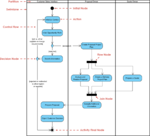
Fork and Join Nodes ⚔️
These nodes control the splitting and merging of control flow within a state machine.
- Fork: Splits one transition into multiple parallel transitions. All target states become active simultaneously.
- Join: Waits for multiple incoming transitions to complete before allowing the flow to continue. This ensures synchronization.
Common Pitfalls and Best Practices ⚠️
Even experienced modelers make mistakes. Adhering to best practices ensures your diagram remains maintainable and understandable.
Pitfall 1: Over-Complexity
Do not try to model the entire system in one diagram. A diagram with 50+ states becomes a “spaghetti diagram” that no one can read. Break your system into smaller, focused state machines for different entities.
Pitfall 2: Unreachable States
Ensure every state is reachable from the initial state. If a state cannot be entered, it serves no purpose and should be removed. Similarly, ensure no state is a “dead end” unless it is the final state.
Pitfall 3: Ambiguous Guards
Avoid guards that are too vague. Use specific boolean logic. If you find yourself writing long sentences in a guard condition, move that logic to an action or a separate method.
Best Practice: Consistent Naming
Use clear, consistent names for states and events. If you use start for one event, do not use begin for another. Consistency reduces cognitive load for developers reading the diagram.
Best Practice: Document Assumptions
Include a legend or a separate notes section explaining specific rules. For example, if a state implies a timeout mechanism, document the duration of that timeout in the notes.
Comparing State Machines with Other UML Diagrams 📊
Understanding where state machines fit in the broader UML ecosystem is important. They complement other diagrams rather than replacing them.
| Diagram Type | Primary Focus | Relationship to State Machine |
|---|---|---|
| Activity Diagram | Workflow and Algorithms | Activity diagrams show the flow of control between actions. State machines show the internal state of the object performing those actions. |
| Sequence Diagram | Interactions Over Time | Sequence diagrams show message exchanges between objects. State diagrams show how an object reacts to those messages internally. |
| Class Diagram | Static Structure | Class diagrams define the attributes and methods. State diagrams define the behavior of those attributes. |
Real-World Application: Authentication Flow 🔐
Let us apply these concepts to a concrete example: a User Authentication System. This scenario demonstrates how state changes manage security and user experience.
State Definitions
- Idle: The system is waiting for input.
- Authenticating: The user has submitted credentials; verification is in progress.
- Locked: Too many failed attempts; access is temporarily denied.
- Active: User is logged in and authenticated.
Transition Logic
- Idle ➔ Authenticating: Event:
loginAttempt(). Action:validateCredentials(). - Authenticating ➔ Active: Event:
credentialsValid. Guard:[isValid]. Action:createSession(). - Authenticating ➔ Locked: Event:
credentialsInvalid. Guard:[attempts >= 3]. Action:lockAccount(). - Authenticating ➔ Idle: Event:
credentialsInvalid. Guard:[attempts < 3]. Action:incrementAttempts(). - Active ➔ Idle: Event:
logout(). Action:clearSession(). - Locked ➔ Idle: Event:
unlockRequest(). Guard:[adminApproved]. Action:resetAttempts().
This logic ensures that the system handles security threats (brute force) while maintaining a clear path for legitimate users. The state machine prevents a user from being in the Active state without passing through Authenticating.
Conclusion and Next Steps 🚀
Modeling state changes is a fundamental skill for system architects and software engineers. By using UML state machine diagrams, you create a blueprint that reduces ambiguity and prevents logic errors during implementation. The diagram acts as a contract between design and development.
As you begin to apply these techniques, start with simple objects and gradually increase complexity. Incorporate history states and orthogonal regions only when necessary to manage concurrency. Remember that the goal is clarity, not artistic expression. A state machine that developers can understand and implement correctly is the only one that matters.
Continue to refine your diagrams based on feedback from the development team. If a state is confusing, simplify it. If a transition is missing, add it. The diagram evolves alongside the software, ensuring that the documentation remains a valuable asset throughout the project lifecycle.
By mastering the nuances of initial states, final states, guards, and actions, you gain the ability to predict system behavior before writing a single line of code. This proactive approach saves time, reduces bugs, and leads to more reliable software architectures.