
Understanding software architecture begins with visualization. Before writing a single line of code, developers and designers map out the structure of their applications. The Unified Modeling Language (UML) serves as the standard for these blueprints. Among the various diagram types, the Class Diagram stands out as the most critical tool for object-oriented design. This guide walks you through the process of creating your first UML class diagram, focusing on clarity, structure, and industry standards. 💻
Whether you are a student learning software engineering or a professional refining your design patterns, mastering the basics of class diagrams is essential. This resource avoids hype and focuses on practical application. We will explore the anatomy of a class, the meaning of relationships, and the steps to construct a diagram that communicates effectively with your team. 🚀
What is a UML Class Diagram? 🤔
A Class Diagram is a static structure diagram in UML. It describes the structure of a system by showing the system’s classes, their attributes, operations (methods), and the relationships among objects. Unlike sequence diagrams that show behavior over time, a class diagram represents the system at a single point in time. It is the backbone of the object-oriented model.
Key characteristics include:
- Static View: It captures the design-time view of a set of objects.
- Structural Detail: It defines the data and behavior of the system.
- Foundation: It serves as the basis for code generation in many tools.
When you draw a class diagram, you are essentially creating a vocabulary for your software. Every class represents a concept, such as a User, an Order, or a Product. By connecting these classes, you define how they interact. This separation of concerns allows teams to discuss complex systems without getting bogged down in syntax immediately. 📝
Anatomy of a Class: The Building Blocks 🧱
Every element in a class diagram follows a specific convention. A standard class rectangle is divided into three compartments. Understanding these sections is the first step to accurate modeling.
1. The Class Name (Top Compartment)
The top section holds the name of the class. This should be a noun, capitalized in a standard format (e.g., Customer or BankAccount). It identifies the blueprint for the objects that will be created. Consistency in naming conventions is vital for readability across the codebase.
2. Attributes (Middle Compartment)
The middle section lists the attributes or properties of the class. These represent the data stored within an object. Examples include name, price, or balance. Each attribute typically includes a visibility modifier and a data type.
Visibility modifiers indicate access levels:
- Public (+): Accessible from any other class.
- Private (-): Accessible only within the class itself.
- Protected (#): Accessible within the class and its subclasses.
- Package (~): Accessible within the same package or namespace.
3. Methods/Operations (Bottom Compartment)
The bottom section details the behaviors or functions of the class. These are the actions the object can perform, such as calculateTotal() or login(). Like attributes, methods also have visibility modifiers. They define the interface through which other objects interact with this class.
A visual example of a single class looks like this:
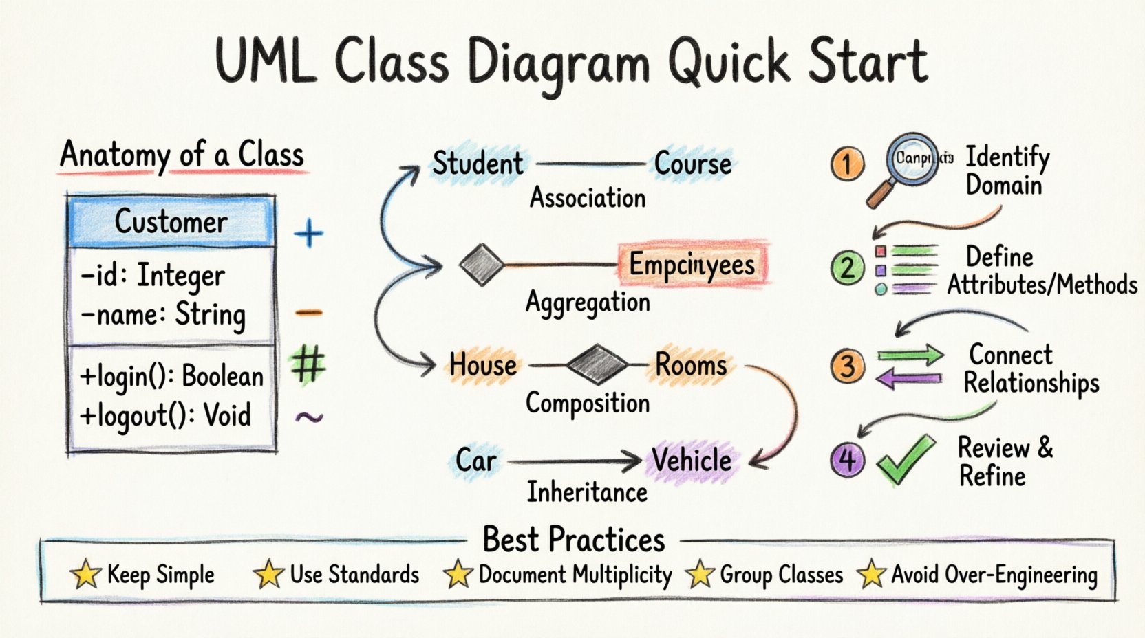
<div>
  Customer
  ------------------
  - id: Integer
  - name: String
  + login(): Boolean
  + logout(): Void
</div>
Notice the use of symbols (+, -) to denote visibility. This shorthand communicates security and access rules instantly to anyone reading the diagram. 🔒
Understanding Relationships: Connecting the Dots 🔗
Classes rarely exist in isolation. They interact through relationships. UML defines four primary types of relationships, each with a specific meaning and notation. Distinguishing between them is crucial for accurate modeling.
1. Association
An association represents a structural link between two classes. It implies that objects of one class are connected to objects of another. A simple line connects the two classes. If the relationship is bidirectional, arrows are not needed on both ends, but directional associations use arrows to show who knows about whom.
Example: A Student enrolls in a Course. The link is an association.
2. Aggregation
Aggregation is a special form of association. It represents a whole-part relationship where the part can exist independently of the whole. Think of it as a “has-a” relationship that is loose. If the whole is destroyed, the part survives.
Example: A Department has Employees. If the department closes, the employees still exist. This is drawn with a hollow diamond at the whole end.
3. Composition
Composition is a stronger form of aggregation. It is a “strong” whole-part relationship. The part cannot exist without the whole. If the owner is destroyed, the parts are destroyed with it.
Example: A House has Rooms. If the house is demolished, the rooms no longer exist as part of that house. This is drawn with a filled diamond at the whole end.
4. Inheritance (Generalization)
Inheritance establishes an “is-a” relationship. A subclass inherits the attributes and methods of a superclass. This allows for code reuse and polymorphism. In the diagram, this is shown as a solid line with a hollow triangle arrow pointing to the superclass.
Example: A Car is a Vehicle. The Car class inherits properties from the Vehicle class.
Relationship Summary Table
| Relationship Type | Notation | Meaning | Example |
|---|---|---|---|
| Association | Solid Line | Structural link | Teacher teaches Student |
| Aggregation | Hollow Diamond | Whole-Part (Independent) | Library has Books |
| Composition | Filled Diamond | Whole-Part (Dependent) | Order has OrderItems |
| Inheritance | Hollow Triangle | Is-A Relationship | Truck is Vehicle |
Understanding these distinctions prevents architectural flaws. Mislabeling a composition as an aggregation can lead to memory leaks or data integrity issues in the actual implementation. 🛠️
Step-by-Step Guide to Drawing Your Diagram 📝
Creating a class diagram is not just about drawing shapes; it is about analyzing requirements and translating them into structure. Follow this logical workflow to ensure your diagram is robust.
Step 1: Identify the Domain
Start by understanding the problem space. What is the system supposed to do? Read the requirements or user stories. Identify the key nouns in the description. These nouns often become your candidate classes.
- Noun: Invoice ➔ Class: Invoice
- Noun: Customer ➔ Class: Customer
- Noun: Payment ➔ Class: Payment
Step 2: Determine Attributes and Methods
For each identified class, brainstorm what data it needs and what actions it can perform. Ask questions like:
- What information does this object hold?
- How does this object interact with others?
- What calculations does it perform?
Filter out unnecessary details. A class diagram should focus on the essential structure, not every single variable.
Step 3: Define Relationships
Connect your classes using the relationship types discussed earlier. Ask how they interact:
- Does one class depend on another?
- Is there a hierarchy?
- Do they share ownership?
Label the lines with multiplicity if necessary. Multiplicity defines how many instances of one class relate to another.
Step 4: Review and Refine
Once the draft is complete, review it for consistency. Check for:
- Circular dependencies (Class A depends on B, B depends on A).
- Redundant attributes (data that belongs to another class).
- Inconsistent naming (using “user” in one place and “customer” in another).
Refinement is an iterative process. Do not hesitate to move elements around to improve layout and clarity. 🧹
Best Practices for Clean Design 🌟
A diagram that is hard to read is useless. Adhering to best practices ensures your documentation remains valuable over time.
1. Keep it Simple
Start with the high-level structure. Avoid adding every single attribute in the initial draft. Focus on the core relationships. You can add detail later as the design evolves. A cluttered diagram obscures the main architecture.
2. Use Standard Conventions
Stick to UML standards for line styles and symbols. Deviating from the standard (e.g., using dashed lines for associations instead of solid) confuses readers who expect specific meanings. Consistency reduces cognitive load.
3. Document Multiplicity
Always define the cardinality of relationships. Is it 1-to-1, 1-to-many, or many-to-many? Notation like 1, 0..*, or 1..* provides critical information about constraints. This helps developers understand data integrity rules without reading the code.
4. Group Related Classes
Use packages or compartments to group related classes. This modularizes the diagram and makes it easier to navigate. It also reflects the package structure in your actual codebase.
5. Avoid Over-Engineering
Do not model every edge case in the initial design. Focus on the happy path. Complex validation logic can be added later. The goal is to communicate the structural backbone, not the logic for every specific scenario.
Common Mistakes to Avoid ⚠️
Even experienced designers make errors. Being aware of common pitfalls can save you time and rework.
- Missing Visibility: Leaving attributes without visibility modifiers creates ambiguity. Always specify public, private, or protected.
- Mixing Relationships: Using a generalization line where an association is needed creates confusion. Ensure the relationship type matches the semantic meaning.
- Ignoring Interfaces: Sometimes a class interacts via an interface rather than directly. If your system relies on abstraction, draw the interface and show the realization relationship (dashed line with hollow triangle).
- Too Many Classes: If a diagram has more than 20-30 classes, it may be too complex to view at once. Consider splitting it into sub-systems or using package diagrams.
- Ignoring Data Types: While not always mandatory, specifying data types (e.g., String, Integer, Date) adds precision to the design and aids in code generation.
From Diagram to Code 🏗️
The ultimate goal of a class diagram is to guide implementation. Once the diagram is finalized, it serves as a reference for writing code. Many development environments support forward engineering, where the diagram can generate skeleton code. However, manual coding is often preferred for flexibility.
When translating the diagram to code:
- Create a file for each class.
- Implement the attributes with the specified visibility and types.
- Write the methods with the correct signatures.
- Establish the relationships using imports, references, or inheritance syntax.
Documentation should evolve with the code. If the implementation changes, update the diagram. An outdated diagram is worse than no diagram at all. It creates false expectations. Regular reviews during sprint planning or code reviews keep the design aligned with reality. 🔄
Advanced Concepts: Interfaces and Abstract Classes 🔮
As your diagrams grow, you will encounter abstract concepts. Abstract classes cannot be instantiated directly; they serve as a base for other classes. They are denoted by italicized names in the diagram. Interfaces define a contract of methods that a class must implement. They are often shown as a separate rectangle with the keyword <<interface>>.
Using interfaces allows for loose coupling. A class depends on the interface, not the concrete implementation. This makes the system more flexible for future changes. For example, a NotificationService might depend on an EmailSender interface. You can swap the implementation to an SMSManager without changing the notification logic. 📱
Final Thoughts on UML Adoption 🎯
Learning to draw UML class diagrams is a skill that pays dividends throughout a career. It forces you to think before you code. It improves communication with stakeholders. It reduces bugs by clarifying data ownership. While it requires practice, the discipline it instills is invaluable.
Start small. Draw a diagram for a simple project. Focus on the relationships. Get comfortable with the notation. As you gain confidence, tackle larger systems. Remember that the diagram is a tool for thought, not just a document for submission. Use it to explore design options and validate your logic. 🧠
By following the steps outlined here, you are well on your way to creating professional-grade architectural diagrams. The foundation is set. The path forward is clear. Happy modeling! ✨