
Unified Modeling Language (UML) stands as the foundational grammar for software architecture. It translates abstract business requirements into concrete technical specifications. However, a diagram alone does not guarantee system integrity. Without a systematic review process, models can become sources of ambiguity rather than clarity. This guide outlines the critical components that require validation during the design phase. By adhering to a structured verification list, architects ensure that blueprints remain actionable and consistent throughout the software lifecycle.
The Importance of Rigorous Verification 🛡️
Software architecture is not merely about drawing shapes and connecting lines. It is about defining relationships, constraints, and behaviors. When a model lacks precision, development teams face rework, integration issues, and timeline delays. A checklist serves as a control mechanism to maintain quality standards. It forces the architect to pause and question assumptions before code is written. This proactive approach reduces technical debt and aligns stakeholders on a single vision.
Verification is not a one-time event. It is a continuous practice that evolves with the project. As requirements shift, the model must adapt without losing its structural coherence. The following sections detail the ten specific elements that demand attention. Each element addresses a specific dimension of system design, from static structure to dynamic behavior.
The 10 Critical Verification Points 🔍
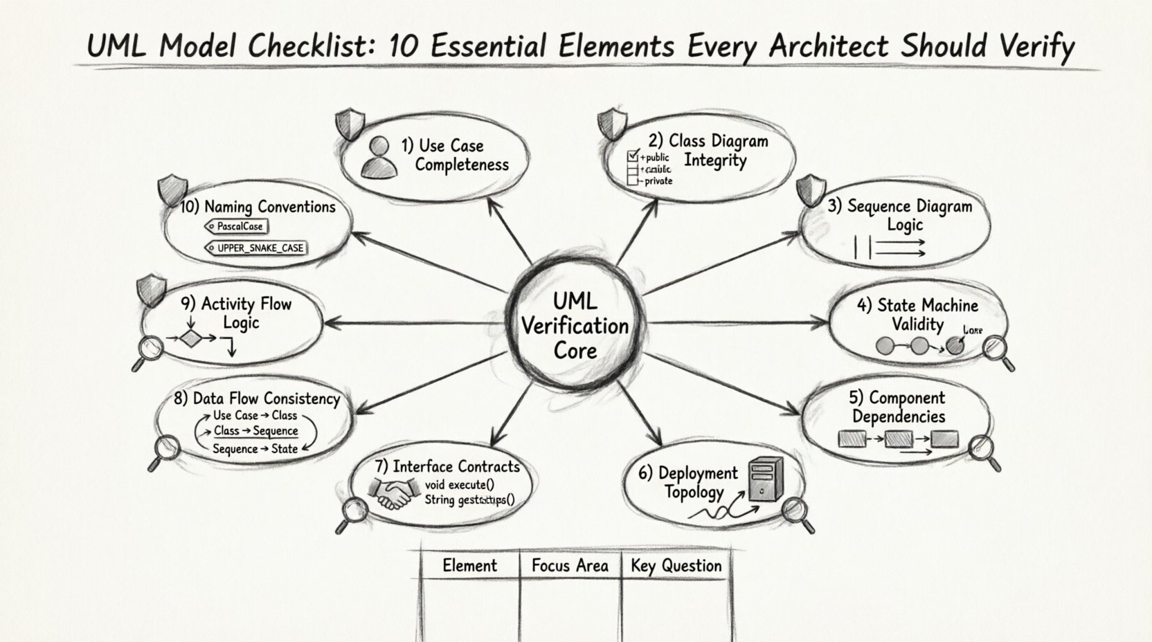
To ensure a robust design, the architect must examine ten distinct areas. These areas cover the spectrum of UML diagram types, including Class, Sequence, State, Component, and Deployment diagrams. Below is a detailed breakdown of what to check for in each category.
1. Use Case Completeness and Clarity ✅
Use cases define the functional scope of the system from the perspective of the actor. They are the entry point for understanding system requirements. Verification begins here because errors in this layer propagate through all downstream diagrams.
- Actor Identification: Ensure all external entities interacting with the system are clearly defined. Distinguish between human users and automated systems.
- Goal Alignment: Each use case must represent a specific user goal. If a use case does not serve a primary actor, it may be unnecessary.
- Pre- and Post-Conditions: Every interaction should have defined entry and exit states. This clarifies the context of the action.
- Extension Points: Verify that alternative flows are documented. This prevents developers from guessing what happens during edge cases.
2. Class Diagram Structural Integrity 🏗️
Class diagrams represent the static structure of the system. They define the data models and the relationships between them. This is often the most frequently referenced diagram by developers during implementation.
- Visibility Modifiers: Check that attributes and methods have correct access levels (public, private, protected). Incorrect visibility leads to coupling issues.
- Association Multiplicity: Verify the cardinality of relationships. Is it one-to-one, one-to-many, or many-to-many? Ambiguity here causes data integrity errors.
- Inheritance Hierarchies: Ensure that polymorphism is used correctly. Avoid deep inheritance trees that make the system rigid and hard to extend.
- Abstract vs. Concrete: Distinguish clearly between interfaces, abstract classes, and concrete implementations.
3. Sequence Diagram Logic and Timing ⏳
Sequence diagrams illustrate how objects interact over time. They are crucial for understanding the flow of control and data exchange. Verification here focuses on the correctness of the message flow.
- Lifeline Existence: Every object involved in the interaction must have a defined lifeline. Missing lifelines indicate incomplete logic.
- Activation Bars: Ensure that objects are active when sending or receiving messages. This clarifies when processing occurs.
- Return Messages: Verify that synchronous calls have corresponding return messages. This ensures the caller knows when the task is complete.
- Loop and Alt Fragments: Check that conditional logic and loops are explicitly marked. This prevents logic errors in the implementation.
4. State Machine Transition Validity 🔄
State diagrams are vital for objects with complex lifecycles, such as orders, payments, or workflows. They define how an object changes behavior based on events.
- Initial and Final States: Every state machine must have a clear start and end point. Undefined termination leads to hanging processes.
- Event Triggers: Ensure that every transition has a defined trigger. No transition should be ambiguous.
- Guard Conditions: Verify that guards are written as boolean expressions. Complex logic should be simplified or moved to code comments.
- Self-Transitions: Check if an object can transition to itself. This is often used for validation or error handling.
5. Component Dependency Mapping 🔗
Component diagrams show the high-level organization of the system. They define the physical or logical building blocks and their dependencies.
- Interface Realization: Verify that components realize the interfaces they depend on. This ensures contract compliance.
- Coupling Analysis: Minimize dependencies between components. High coupling makes the system fragile and hard to maintain.
- Package Organization: Ensure components are grouped logically. This aids in modular development and testing.
- External Dependencies: Document all external libraries or services. This prevents build failures due to missing resources.
6. Deployment Topology Accuracy 🖥️
Deployment diagrams map the software artifacts to the hardware infrastructure. They are essential for understanding the runtime environment.
- Node Configuration: Verify that nodes represent actual hardware or virtual environments. Do not mix logical and physical layers without distinction.
- Communication Paths: Ensure that communication protocols (e.g., HTTP, TCP) are specified between nodes.
- Artifact Placement: Check that software artifacts are deployed to the correct nodes. This avoids runtime configuration errors.
- Network Security: Indicate firewalls or security zones if applicable. This is critical for enterprise architectures.
7. Interface Contract Definition 🤝
Interfaces define the interaction points between components. They act as the contract that guarantees behavior regardless of implementation.
- Method Signatures: Verify that input and output parameters match across all interface definitions.
- Exception Handling: Document expected exceptions. This ensures error handling is consistent across the system.
- Protocol Compliance: Ensure that interface usage aligns with the chosen architectural style (e.g., REST, RPC).
- Versioning Strategy: Plan for interface evolution. Versioning prevents breaking changes for consumers.
8. Data Flow Consistency Across Models 📊
Data flow must be consistent whether viewed through a class diagram, sequence diagram, or activity diagram. Inconsistency leads to data loss or corruption.
- Entity Alignment: Ensure that data entities in the class diagram match the data passed in sequence diagrams.
- Transformation Logic: Verify that data transformations are clearly defined in activity diagrams.
- Storage Requirements: Confirm that data persistence is addressed in deployment and component diagrams.
- Null Handling: Check how null values are treated in data flows. This prevents runtime exceptions.
9. Activity Flow Logic and Control Points 📈
Activity diagrams describe the workflow and business processes. They focus on the flow of control rather than object interaction.
- Fork and Join: Verify that parallel processes are synchronized correctly. Asynchronous flows need clear join points.
- Decision Nodes: Ensure all branches from decision nodes lead to a valid state. Avoid dead ends in the logic.
- Object Flows: Check that objects are created and destroyed at appropriate times. This manages resource usage.
- Exception Paths: Document error handling paths within the workflow. This ensures robustness.
10. Naming Conventions and Standardization 🏷️
Naming is the foundation of readability. Inconsistent naming makes a model difficult to understand and maintain.
- Class Naming: Use nouns for classes. Avoid verbs unless they represent actions or behaviors.
- Method Naming: Use verbs for methods. Ensure they follow a consistent prefix or suffix style.
- Package Naming: Use a hierarchical structure for packages. This reflects the domain structure.
- Documentation Tags: Ensure all elements have clear labels. Avoid generic names like “Element1” or “ObjectA”.
Common Modeling Pitfalls 🚧
Even with a checklist, architects can fall into traps that compromise model quality. Recognizing these pitfalls early saves significant time during development.
- Over-Engineering: Creating diagrams that are too detailed for the current phase. This slows down communication.
- Inconsistency: Using different symbols or notation styles within the same document. This confuses readers.
- Outdated References: Failing to update models when code changes. This leads to a disconnect between documentation and reality.
- Ignoring Non-Functional Requirements: Focusing only on features while neglecting performance, security, and scalability.
Integrating the Checklist into Workflow 🔄
Verification should not be a post-design activity. It must be embedded into the design process itself. This ensures that quality is built in rather than inspected in.
- Design Reviews: Schedule regular sessions where the checklist is used as the agenda.
- Automated Validation: Where possible, use tools to check syntax and structural rules.
- Peer Review: Have another architect review the model. Fresh eyes often catch missed elements.
- Feedback Loops: Collect feedback from developers who consume the models. They can identify ambiguities.
Long-Term Model Maintenance 📅
A model is a living artifact. It requires maintenance just like the code it represents. Without a strategy for upkeep, the model becomes obsolete quickly.
- Version Control: Store model files in a version control system. Track changes over time.
- Change Management: Link model changes to requirement changes. This maintains traceability.
- Archiving: Archive old versions for historical reference. This helps in auditing and future planning.
- Documentation Updates: Keep the accompanying documentation synchronized with the diagrams.
Summary of Essential Elements 📋
The table below summarizes the ten elements and their primary focus areas. This serves as a quick reference for architects during the design phase.
| Element | Focus Area | Key Verification Question |
|---|---|---|
| Use Cases | Functional Scope | Do all actors have clear goals? |
| Class Diagrams | Static Structure | Are relationships and types correct? |
| Sequence Diagrams | Interaction Flow | Is the message order logical? |
| State Machines | Object Lifecycle | Are all transitions defined? |
| Component Diagrams | System Organization | Are dependencies minimized? |
| Deployment Diagrams | Infrastructure | Is the topology accurate? |
| Interface Contracts | Integration Points | Do signatures match? |
| Data Flow | Information Consistency | Is data handled consistently? |
| Activity Flow | Process Logic | Are control points clear? |
| Naming | Readability | Are names descriptive and standard? |
Adopting this checklist ensures that the UML models serve their intended purpose. They become reliable guides for development rather than just documentation artifacts. By focusing on these ten elements, architects can build systems that are robust, maintainable, and aligned with business needs. The effort invested in verification pays dividends in reduced rework and higher quality software delivery.