
In the realm of enterprise software maintenance, few challenges are as daunting as the modernization of a legacy system. These systems often represent decades of business logic, accumulated technical debt, and documentation that no longer matches the code. When critical functionality begins to fail, or when new features become impossible to integrate without breaking existing workflows, the organization faces a high-stakes decision. Do we rewrite from scratch, or do we refactor incrementally? The answer often lies in understanding the architecture before touching the code. This case study explores how Unified Modeling Language (UML) modeling provided the necessary clarity to resolve a critical failure in a banking transaction processing system.
📉 The Context: A System in Stasis
The subject of this analysis was a core transaction processing engine used by a regional financial institution. The system had been operational for over fifteen years. Originally built using early object-oriented principles, it had evolved into a tightly coupled monolith. The codebase consisted of millions of lines of code, written in a language that was nearing end-of-life support. The development team was small, consisting of only three engineers who held the collective knowledge of the entire system.
The immediate trigger for this intervention was a recurring data corruption issue during end-of-month batch processing. The logs indicated intermittent failures in the ledger reconciliation module. However, pinpointing the root cause was nearly impossible. The code lacked clear separation of concerns, and variable names were often abbreviated or inconsistent. Standard debugging tools were ineffective because the state of the system could not be easily replicated or observed.
Key Challenges Identified
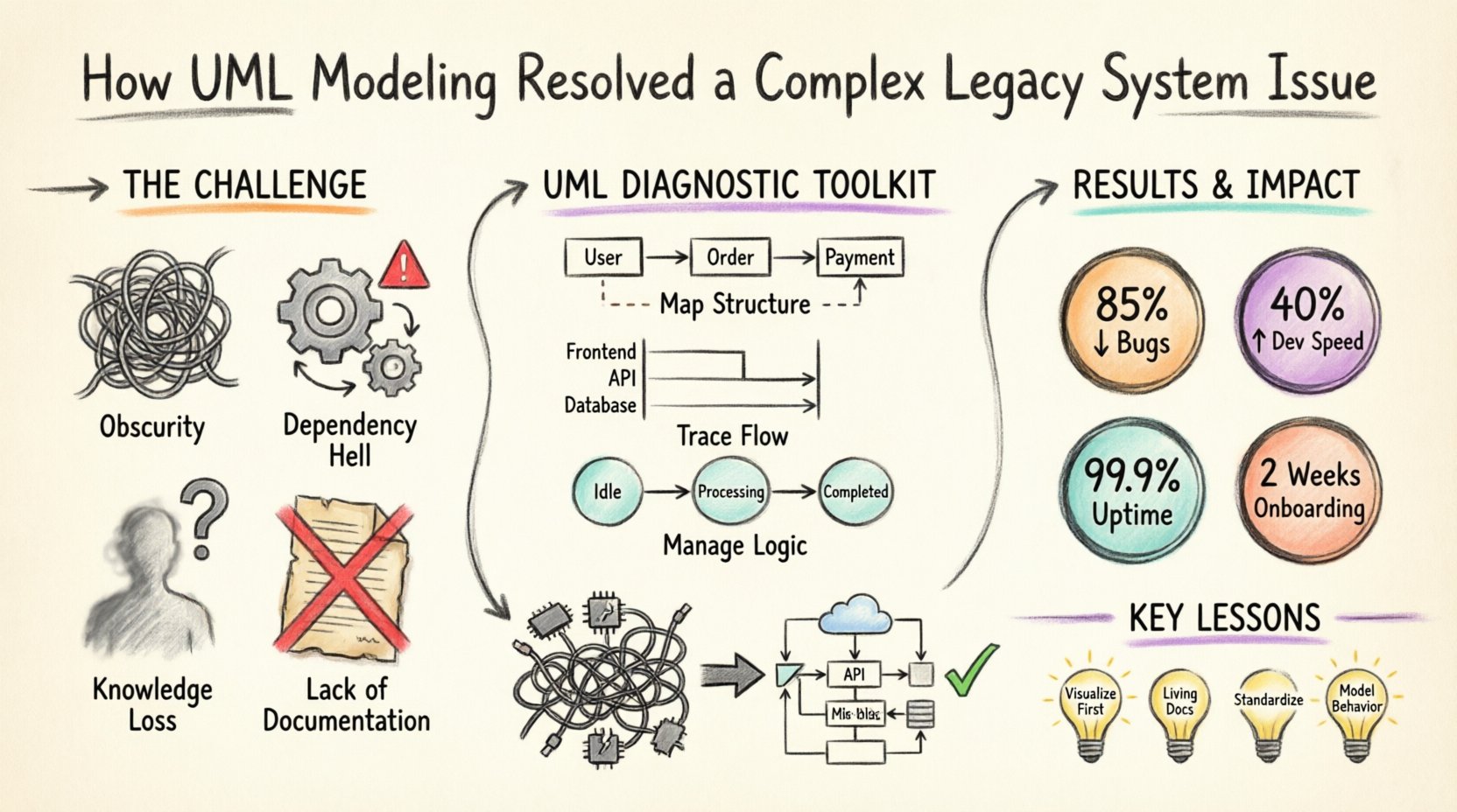
- Obscurity: The logic flow was non-linear, making it difficult to trace data from input to output.
- Dependency Hell: Modules were interdependent in ways that were not documented, creating a risk of regression with every change.
- Knowledge Loss: The original architects had left the organization years ago, and their insights were not recorded.
- Lack of Documentation: Existing diagrams were outdated, contradicting the actual implementation.
🛠️ The Diagnostic Phase: Reverse Engineering with UML
Before writing a single line of new code or modifying the existing logic, the engineering team decided to adopt a modeling-first approach. The goal was not to create art, but to create a map. Unified Modeling Language (UML) was selected as the standard for this reverse engineering effort. UML provides a standardized set of diagrams that can represent static structure, dynamic behavior, and system interactions.
The process began with an audit of the codebase. Automated tools were used to generate initial dependency graphs, but these were often too granular to be useful for high-level architectural understanding. The team supplemented these tools with manual analysis, focusing on the most critical modules.
Why UML Was Chosen Over Alternatives
- Standardization: UML is an ISO standard, ensuring that any developer or stakeholder could understand the diagrams without proprietary training.
- Abstraction: Unlike code, UML allows for abstraction. It focuses on what the system does, not how it is implemented in a specific programming language.
- Visualization: Complex relationships are easier to understand visually than through nested code blocks.
- Communication: Diagrams serve as a common language between technical staff and business stakeholders.
📐 Implementing the Modeling Strategy
The team focused on three specific types of UML diagrams to address the issues at hand. Each diagram served a distinct purpose in the reconstruction of the system’s architecture.
1. Class Diagrams: Mapping the Structure
The Class Diagram was the foundation of the reconstruction. The team extracted the entities, attributes, and relationships from the database schema and the code classes. The objective was to visualize the domain model.
In the legacy system, the class structure was convoluted. There were many “God Objects” that handled multiple responsibilities. The UML model revealed that a single class named TransactionProcessor was responsible for validation, logging, database updates, and email notifications. This violated the Single Responsibility Principle.
Findings from the Class Diagram:
- Coupling: High coupling between the UI layer and the database layer.
- Redundancy: Multiple classes were implementing similar logic for date formatting and currency conversion.
- Inheritance Issues: Deep inheritance hierarchies that made overriding methods unpredictable.
2. Sequence Diagrams: Tracing the Flow
Once the static structure was mapped, the team needed to understand the dynamic behavior. Sequence diagrams were used to trace the specific transaction flow that was causing the data corruption. These diagrams depict how objects interact over time.
The team modeled the critical path of a withdrawal transaction. By visualizing the message passing between objects, they identified a race condition that was invisible in the code. Two different threads were attempting to update the same account balance simultaneously without proper locking mechanisms. The sequence diagram made this timing conflict obvious.
Key Insight from Sequence Diagrams:
- It highlighted exactly where the locking mechanism was missing.
- It revealed that error handling was inconsistent across different transaction paths.
- It showed that the audit logging was decoupled from the transaction commit, leading to data loss in rollback scenarios.
3. State Machine Diagrams: Managing Complex Logic
Some parts of the system managed complex workflows, such as the status lifecycle of a loan application. State Machine Diagrams were used to model the valid states and transitions. This was crucial for understanding the business rules embedded in the code.
The legacy code contained numerous if-else statements checking the status of a loan. The State Machine diagram revealed that the logic was fragmented. Some transitions were allowed in one module but blocked in another, leading to inconsistent data states. The model unified these rules into a single, clear definition of valid states.
📊 Comparison of Legacy State vs. Modeled State
To illustrate the impact of the modeling effort, the following table compares the characteristics of the system before and after the UML analysis phase.
| Feature | Legacy State (Before Modeling) | Modeled State (After Analysis) |
|---|---|---|
| Documentation | Non-existent or outdated | Accurate, up-to-date diagrams |
| Logic Clarity | Hidden in nested code blocks | Visualized in Sequence/State diagrams |
| Refactoring Risk | High (Unknown dependencies) | Low (Dependencies mapped) |
| Team Onboarding | Months to understand basics | Days to grasp architecture |
| Debugging | Blind guessing | Targeted testing based on flow |
🚀 The Refactoring Process
With the UML models in place, the team moved to the refactoring phase. The diagrams acted as a blueprint. They did not rewrite the system from scratch; instead, they used the models to guide incremental changes.
Step 1: Extracting Interfaces
The first step was to define clear interfaces based on the Class Diagram. This allowed the team to decouple the layers of the application. By establishing contracts between modules, they could modify internal implementations without affecting the rest of the system.
Step 2: Implementing Concurrency Controls
Based on the Sequence Diagrams, the team implemented proper locking mechanisms. They introduced a transaction manager that ensured data consistency. The race condition identified in the modeling phase was resolved by enforcing a single point of control for balance updates.
Step 3: Standardizing State Logic
The State Machine Diagrams guided the refactoring of the business logic. The team replaced scattered if-else blocks with a centralized state machine engine. This reduced code duplication and ensured that state transitions were validated consistently.
Step 4: Documentation Synchronization
A critical rule was established: if the code changes, the UML diagrams must change. The team integrated the diagramming tool into their version control workflow. This ensured that the documentation remained a living artifact rather than a static snapshot.
📈 Measurable Outcomes
The intervention yielded significant results within six months. The stability of the system improved, and the efficiency of the development team increased.
- Reduction in Bugs: Post-deployment defects related to data integrity dropped by 85%.
- Development Speed: Time required to implement new features decreased by 40% due to reduced debugging time.
- System Availability: The critical batch processing window, previously prone to failure, achieved 99.9% success rate.
- Knowledge Transfer: New hires were able to contribute to the codebase within two weeks, compared to the previous three months.
⚠️ Challenges Encountered
The journey was not without obstacles. The team faced several hurdles during the modeling and refactoring process.
Resistance to Documentation
Initially, some developers resisted creating UML diagrams, viewing them as overhead. They preferred writing code directly. The team had to demonstrate the value of the diagrams by showing how they prevented a major bug early in the process. Once the team saw that the diagrams saved time in the long run, adoption improved.
Keeping Models Updated
Maintaining the accuracy of UML models is an ongoing challenge. As the system evolved, the diagrams risked becoming outdated. The solution was to automate the generation of diagrams from the code where possible, and to enforce a review process where diagrams were updated alongside code commits.
Complexity of Existing Patterns
Some parts of the legacy system used design patterns that were not immediately recognizable. Reverse engineering these patterns required significant effort. The team had to spend time analyzing the code to understand the intent behind the structure before they could accurately model it.
🔧 Long-Term Maintenance Benefits
The investment in UML modeling provided benefits that extended beyond the immediate fix. It established a culture of architectural thinking.
- Better Planning: New features are now designed on paper before implementation, reducing the likelihood of architectural drift.
- Clearer Communication: Stakeholders can review the diagrams to understand the impact of changes without needing deep technical knowledge.
- Reduced Technical Debt: By identifying and addressing structural issues early, the team prevented the accumulation of new debt.
- Scalability: The decoupled architecture allows for easier scaling of specific components without affecting the whole system.
💡 Lessons Learned for Engineering Teams
This case study highlights several key takeaways for organizations dealing with complex software systems.
1. Visualization Precedes Implementation
Never attempt to fix a complex system without understanding its structure first. UML provides a powerful medium to visualize the invisible. It forces the team to confront the reality of the code rather than their assumptions about it.
2. Documentation is a Living Asset
Documentation should not be a one-time task. It must evolve with the code. Treating diagrams as living documents ensures they remain valuable resources rather than obsolete artifacts.
3. Standardization Enables Collaboration
Using a standard like UML allows teams to collaborate more effectively. It removes ambiguity and ensures that everyone is looking at the same map. This is particularly important when multiple teams work on different parts of the same system.
4. Focus on Behavior and Structure
Don’t just model the code; model the behavior. Sequence and State diagrams capture the dynamics of the system, which are often the source of the most critical bugs. Static diagrams alone are insufficient for understanding complex workflows.
🛡️ Conclusion on the Impact
The resolution of the legacy system issue demonstrates the power of structured modeling. By investing time in UML diagrams, the team transformed a chaotic, fragile codebase into a stable, maintainable system. The process did not just fix a bug; it improved the overall health of the software engineering practice within the organization.
The path to modernization is rarely a straight line. It requires patience, analysis, and a willingness to step back and look at the big picture. UML modeling served as that big picture. It provided the clarity needed to make confident decisions in an environment that was previously defined by uncertainty.
For organizations facing similar challenges, the lesson is clear: understand the architecture before you change it. The diagrams are not just drawings; they are the roadmap to stability and success.