
The landscape of software engineering has shifted dramatically. Where monolithic applications once reigned supreme, distributed systems now define the standard. This transition demands a re-evaluation of the tools we use to plan and visualize these complex structures. Unified Modeling Language (UML) has long been the backbone of system design, yet the dynamic nature of cloud computing challenges traditional static diagrams. This guide explores how modeling techniques must evolve to remain relevant in a world defined by microservices, containerization, and continuous deployment.
Understanding the Shift: From Static to Dynamic 🔄
Traditional UML was designed for a time when software lifecycles were linear. Waterfall methodologies dominated, and diagrams served as blueprints that remained static throughout development. Today, architectures are fluid. Services scale up and down based on demand. Infrastructure is ephemeral. Relying solely on static sequence diagrams or class diagrams often fails to capture the runtime behavior of modern applications.
- Monolithic Thinking: Traditional UML assumes a fixed set of components that interact in predictable ways.
- Cloud Reality: Modern systems involve auto-scaling groups, load balancers, and transient containers.
- The Gap: There is a disconnect between the design-time model and the runtime environment.
To bridge this gap, engineers must adapt their modeling approach. The goal is not to discard UML but to extend its utility. We need diagrams that reflect state, concurrency, and data flow in a distributed context.
Key Diagrams for Cloud-Native Design ☁️
Not every standard UML diagram holds equal weight in a cloud environment. Certain types provide more value when visualizing distributed systems. Below is an overview of which diagrams to prioritize and how to modify them for modern needs.
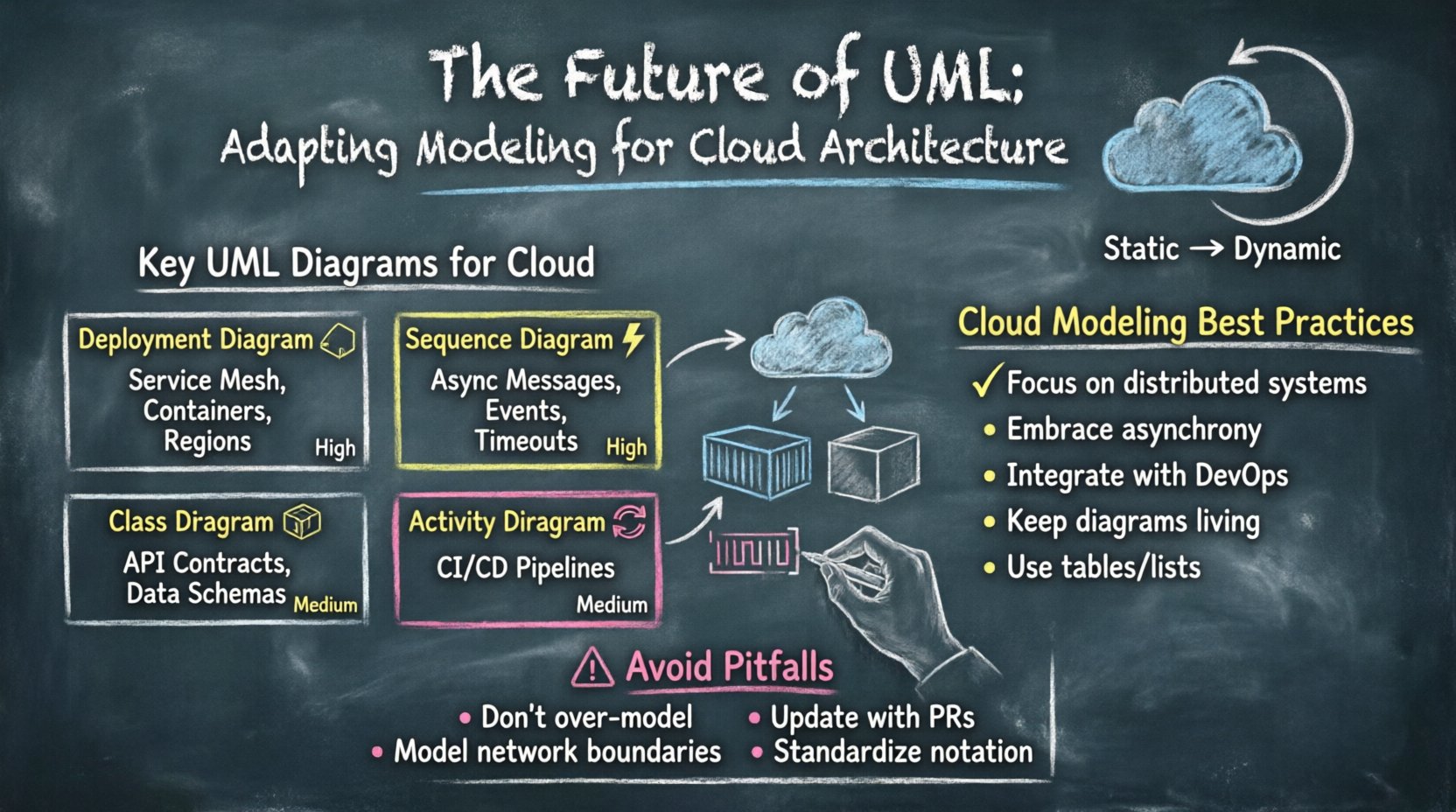
| Diagram Type | Traditional Use | Cloud Adaptation | Relevance |
|---|---|---|---|
| Deployment Diagram | Server-to-server mapping | Service mesh and container nodes | High |
| Sequence Diagram | Linear method calls | Asynchronous messaging and events | High |
| Class Diagram | Object relationships | API contracts and data schemas | Medium |
| Activity Diagram | Workflow logic | CI/CD pipelines and orchestration | Medium |
1. Deployment Diagrams: Visualizing Infrastructure 🏗️
In cloud architecture, the deployment diagram becomes critical. However, the nodes on these diagrams change. Instead of physical servers, we now model logical nodes representing clusters, regions, or availability zones.
- Regions and Zones: Map out the geographical distribution of services to ensure resilience.
- Container Clusters: Represent groups of containers rather than individual pods.
- External Interfaces: Clearly define how services interact with third-party APIs or public gateways.
When creating these models, focus on connectivity. How does traffic flow between the load balancer and the backend? How does data replicate across regions? Visualizing these paths helps identify single points of failure before they impact production.
2. Sequence Diagrams: Handling Asynchrony ⚡
Microservices often communicate via message queues or event streams rather than direct HTTP requests. Traditional sequence diagrams imply a synchronous wait for a response. To adapt, we must represent asynchronous messages clearly.
- Message Arrows: Use dashed lines to denote fire-and-forget events.
- Activation Bars: Extend activation bars to show long-running processes.
- Timeouts: Indicate retry mechanisms and timeout thresholds within the flow.
By explicitly modeling the waiting periods and event handlers, teams can better understand latency implications and error handling strategies.
3. Component Diagrams: Defining Boundaries 🧱
Component diagrams help define the boundaries of microservices. In a distributed system, clear boundaries are essential to prevent tight coupling. These diagrams should outline:
- Internal logic vs. external exposure.
- Data ownership and access rights.
- API endpoints and their consumers.
When a component diagram is well-structured, it acts as a contract. Other teams can integrate with the service without needing to know the internal implementation details. This separation of concerns is vital for independent deployment cycles.
Microservices and Modeling Challenges 🧩
Adopting a microservices architecture introduces complexity that static diagrams struggle to capture. The sheer number of services can make a single diagram unreadable. Here are strategies to manage this complexity.
Decomposing the Model
Do not attempt to model the entire system in one view. Break the architecture down by business capability or domain. This approach, often aligned with Domain-Driven Design, allows for multiple diagrams that cover specific areas.
- Context Diagram: A high-level view of the entire ecosystem.
- Service Diagrams: Detailed views of individual domains.
- Interaction Diagrams: Specific flows between services.
Data Consistency and Transactions
In monolithic systems, ACID transactions are straightforward. In cloud-native environments, distributed transactions require different modeling approaches. You must visualize how data integrity is maintained across services.
- Sagas: Model long-running transactions as a series of local transactions.
- Eventual Consistency: Indicate where data might temporarily differ across nodes.
- Compensating Actions: Show how to reverse a process if a step fails.
These elements are crucial for ensuring reliability. If a diagram does not show how errors are handled, it is incomplete.
Integrating Modeling with DevOps 🛠️
The gap between design and operations has traditionally been wide. In modern cloud environments, this gap must close. Modeling should not be a separate phase that happens once at the beginning. It must be integrated into the DevOps lifecycle.
Infrastructure as Code (IaC)
Infrastructure is now defined by code. While UML diagrams describe the intent, IaC defines the reality. There is a need to align these two. Some teams use diagrams to generate scaffolding for IaC templates. Others use IaC to validate diagram assumptions.
- Validation: Check if the deployed infrastructure matches the design model.
- Documentation: Use diagrams to explain IaC configurations to new team members.
- Change Management: Update diagrams when infrastructure changes occur.
Continuous Integration Pipelines
When code is merged, the deployment pipeline runs. Modeling should support this flow. Diagrams can help identify which services need to be tested when a change is made.
- Impact Analysis: Visualize dependencies to determine test scope.
- Rollback Strategies: Diagram the steps required to revert a deployment.
- Monitoring: Map metrics to specific components in the diagram.
This integration ensures that the model remains a living document rather than a static artifact that sits on a server.
Dynamic Modeling for Runtime Behavior 📈
Static diagrams show what the system should do. Dynamic modeling shows what the system does. In cloud environments, runtime behavior is unpredictable. Auto-scaling, network partitions, and resource contention are common occurrences.
State Diagrams
State diagrams are often overlooked but are highly effective for modeling the lifecycle of a resource. For example, a cloud function might transition through states like Initializing, Running, Erroring, and Terminating.
- Event Triggers: Define what causes the state change.
- Actions: Specify what occurs during the transition.
- Guards: Show conditions that prevent a transition.
This level of detail helps in designing robust error handling and logging mechanisms.
Performance Modeling
Performance is a non-functional requirement that must be modeled. While UML does not natively support performance metrics, extensions exist. Teams can annotate diagrams with latency expectations or throughput limits.
- Load Estimation: Indicate expected traffic volumes per service.
- Bottlenecks: Highlight components that might slow down the system.
- Resource Constraints: Note memory or CPU limits for specific nodes.
By incorporating these constraints early, architects can make informed decisions about resource allocation.
Common Pitfalls and How to Avoid Them ⚠️
Even with the best intentions, modeling efforts can fail. Understanding common pitfalls helps teams stay on track.
1. Over-Modeling
Creating detailed diagrams for every minor component leads to maintenance overhead. If a diagram takes longer to update than the code changes, it becomes obsolete.
- Solution: Focus on high-level architecture and critical flows. Keep details in the code comments.
2. Ignoring the Network
Cloud services communicate over networks that can fail. Diagrams often assume perfect connectivity.
- Solution: Explicitly model network boundaries, firewalls, and potential latency issues.
3. Stale Documentation
Diagrams created during the design phase are often forgotten after deployment.
- Solution: Make diagram updates part of the pull request review process.
4. Lack of Standardization
When every engineer draws diagrams differently, the documentation becomes confusing.
- Solution: Establish a team standard for notation, colors, and symbols.
The Future of Modeling Tools 🛠️🔮
As cloud technologies evolve, so must the tools we use to model them. We are moving towards more automated and code-centric approaches.
- Model-Driven Development: Tools that generate infrastructure code directly from diagrams.
- Visual Programming: Drag-and-drop interfaces that compile into executable logic.
- AI-Assisted Design: Algorithms that suggest optimal architectures based on requirements.
These advancements aim to reduce the manual effort required to keep models accurate. The goal is to make modeling a seamless part of the development workflow rather than a separate burden.
Strategies for Adoption 📊
Implementing these adapted modeling techniques requires a shift in culture. Here is how teams can approach this transition effectively.
- Start Small: Begin with one critical service or domain. Prove the value before expanding.
- Involve Operations: Include DevOps engineers in the modeling process to ensure practicality.
- Automate Updates: Use scripts to keep diagrams synchronized with code repositories.
- Train the Team: Ensure everyone understands the new conventions and tools.
By taking a gradual approach, teams can avoid resistance and ensure long-term adoption.
Summary of Best Practices ✅
To summarize the key takeaways for adapting UML to modern cloud architecture:
- Focus on Distributed Systems: Prioritize diagrams that show service interaction and data flow.
- Embrace Asynchrony: Model event-driven architectures accurately.
- Integrate with DevOps: Keep models in sync with the deployment pipeline.
- Keep it Living: Treat diagrams as code that requires maintenance.
- Use Tables and Lists: Structure information clearly for quick reference.
The future of UML lies in its ability to evolve. By adapting these techniques, organizations can maintain clarity and control over increasingly complex systems. The core principles of modeling remain valid, but the execution must change to meet the demands of the cloud.
Staying updated with these practices ensures that architecture remains robust, scalable, and maintainable. As the industry moves forward, the ability to visualize and plan within a dynamic environment will be a defining skill for technical leaders.