
Unified Modeling Language serves as the universal grammar for software architecture. It bridges the gap between abstract requirements and concrete implementation. However, the precision required to maintain a valid diagram is often underestimated. When notations are applied incorrectly, the resulting models become sources of ambiguity rather than clarity. This guide addresses the specific friction points that arise when interpreting or creating UML symbols. We will dissect common errors, clarify semantic distinctions, and establish a rigorous workflow for diagram validation.
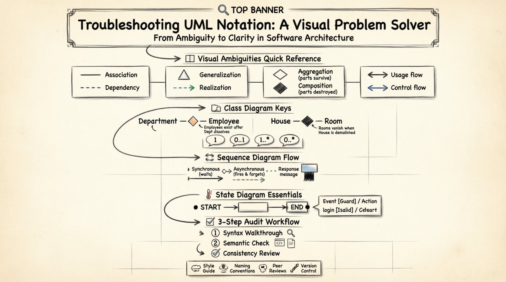
Confusion often stems from the similarity of visual markers. A solid line may imply a relationship, while a dashed line suggests dependency. A filled diamond indicates composition, whereas a hollow diamond suggests aggregation. These subtle differences carry significant weight regarding object lifecycles and coupling. If these distinctions are ignored, the architectural blueprint fails to reflect the intended system behavior. This document provides a systematic approach to identifying and correcting these issues without relying on automated tools.
🧐 Understanding the Language of Diagrams
Before troubleshooting, one must understand the foundational rules. UML is not merely a drawing tool; it is a formal specification. Every line, arrow, and shape adheres to a standard defined by the Object Management Group. Deviations from these standards introduce interpretation risks. When a developer sees a diagram, they should be able to predict system behavior without asking the creator for clarification.
- Syntax Validity: The diagram must follow the structural rules of the specific diagram type (e.g., Class, Sequence).
- Semantic Accuracy: The relationships depicted must match the actual logic of the software.
- Consistency: Symbols must be used uniformly across the entire documentation set.
When troubleshooting, start by verifying syntax. Is the arrowhead correct for the relationship? Is the label placed in the standard location? Once syntax is confirmed, move to semantics. Does the relationship truly exist in the code? Is the direction of flow logical?
📐 Common Visual Ambiguities
Certain symbols are frequently misused due to their visual proximity. A thorough audit requires a close examination of line styles and arrowheads. The following table outlines the most frequent points of confusion.
| Symbol Feature | Meaning A | Meaning B | Visual Distinction |
|---|---|---|---|
| Line Style | Association | Dependency | Solid vs. Dashed |
| Arrowhead | Generalization | Realization | Hollow Triangle vs. Dashed Arrow |
| Diamond Shape | Aggregation | Composition | Hollow vs. Filled |
| Arrow Direction | Usage | Control Flow | Direction of the head |
Line Styles and Connectivity
The distinction between a solid line and a dashed line is the most common source of error. A solid line typically denotes a structural relationship, such as an Association. This implies that one object holds a reference to another. A dashed line usually represents a Dependency. This implies a temporary relationship or a usage of an interface without structural ownership.
When troubleshooting, check the lifecycle. If the ‘client’ object is destroyed while the ‘supplier’ object continues to exist, a Dependency is appropriate. If the ‘client’ object is a container of the ‘supplier’ object, an Association or Composition is required. Mixing these up leads to incorrect assumptions about memory management and object persistence.
Arrowheads and Inheritance
Triangle arrowheads are used for inheritance and implementation. A hollow triangle pointing to a parent class indicates Generalization (Inheritance). This means the child class inherits attributes and methods from the parent. A dashed line with a hollow triangle indicates Realization. This means a class implements an interface.
- Generalization: Use a solid line with a hollow triangle. The child IS-A the parent.
- Realization: Use a dashed line with a hollow triangle. The class DOES the interface.
Confusion often arises when a dashed line is used for inheritance or a solid line for implementation. This violates the standard notation and can lead developers to assume a structural hierarchy where none exists.
🏗️ Class Diagram Deep Dive
Class diagrams are the backbone of structural modeling. They define the static structure of the system. Troubleshooting here requires a focus on multiplicity and relationship types.
Aggregation vs. Composition
This is the most critical distinction in class modeling. Both use diamond shapes on the line connecting two classes, but the fill state changes the meaning entirely.
- Aggregation (Hollow Diamond): Represents a “Has-A” relationship where the parts can exist independently of the whole. If the whole is destroyed, the parts remain. Example: A Department has Employees. If the Department dissolves, the Employees still exist.
- Composition (Filled Diamond): Represents a stronger ownership. The parts cannot exist independently of the whole. If the whole is destroyed, the parts are destroyed. Example: A House has Rooms. If the House is demolished, the Rooms cease to exist.
When reviewing a diagram, ask: Can the child object survive the deletion of the parent object? If the answer is yes, the diamond should be hollow. If the answer is no, the diamond should be filled. Ambiguity here leads to memory leak risks or orphaned data issues in the actual codebase.
Multiplicity Notation
Numbers placed near the ends of association lines define how many instances of a class relate to another. Common errors include missing numbers or incorrect ranges.
- 1: Exactly one instance.
- 0..1: Zero or one instance (optional).
- 1..*: One or more instances (mandatory).
- 0..*: Zero or more instances (optional collection).
Incorrect multiplicity can imply mandatory relationships where optional ones are intended, or vice versa. Always verify the business rules. Does a User have to have an Address? If not, use 0..1. Does a Cart have to contain items? If the cart is empty, it might be 0..*.
🔄 Sequence Diagram Logic
Sequence diagrams model dynamic behavior over time. They focus on the flow of messages between objects. Troubleshooting these diagrams involves checking the timing and type of messages.
Activation Bars
Rectangles on object lifelines indicate the period during which an object is performing an action. A common error is omitting activation bars for complex methods. If a method calls another method, the activation bar should extend to cover the duration of the call.
- Start of Bar: Message entry or self-call initiation.
- End of Bar: Message return or completion of the action.
If a bar is missing, it is unclear when the object becomes active. This hinders performance analysis and thread synchronization planning.
Message Types
Arrows between lifelines represent messages. The line style indicates the synchronization type.
- Synchronous (Solid Arrow): The caller waits for the callee to finish before proceeding. Use a solid line with a filled arrowhead.
- Asynchronous (Solid Line with Open Arrowhead): The caller sends the message and continues without waiting. Use a solid line with an open arrowhead.
- Return Message (Dashed Line): Indicates the response returning to the caller. Use a dashed line with an open arrowhead pointing back.
A frequent mistake is using synchronous arrows for async operations. This suggests blocking behavior that does not exist in the code. Conversely, using async arrows for synchronous calls implies potential race conditions where the caller does not wait for a result.
🌡️ State Diagram Nuances
State diagrams describe the lifecycle of a single object. They are essential for complex controllers or workflow entities. Errors here often involve the definition of initial and final states.
Entry and Exit Points
The initial state is represented by a filled black circle. The final state is a black circle with a border. Confusion occurs when multiple entry points are used without a clear start node.
- Initial Node: Must exist. It is the starting point of all flows.
- Final Node: Can be multiple, but each represents a distinct end condition.
Ensure that every path leads to a final node. Dead ends in a state diagram indicate a system that can hang indefinitely. This is a critical logic error.
Transition Labels
Arrows between states are transitions. They are labeled with the event that triggers the move. The label format is typically Event [Guard] / Action.
- Event: What triggered the change?
- Guard: Conditions that must be met (e.g., [isAuthorized]).
- Action: What happens during the transition (e.g., logUser).
Missing guards can lead to states being entered when they shouldn’t be. Missing actions can hide side effects. Every transition should be fully documented to ensure the state machine behaves predictably.
📋 Audit and Correction Workflow
Once the specific notation errors are identified, a systematic process is needed to fix them. Manual review is the most effective method when software tools are not utilized for validation.
Step 1: The Syntax Walkthrough
Scan the entire diagram for rule violations. Check every line, shape, and label against the UML standard.
- Are all class names capitalized?
- Are attributes and methods separated by a line?
- Are visibility symbols (+, -, #) used correctly?
- Are arrows pointing in the direction of dependency?
Step 2: The Semantic Check
Compare the diagram against the code or requirements specification.
- Does the code actually use inheritance where the diagram shows it?
- Are the relationship cardinalities correct in the database schema?
- Do the sequence flows match the actual execution order?
Step 3: The Consistency Review
Ensure the diagram matches the rest of the documentation.
- Are naming conventions consistent across all diagrams?
- Is the level of detail the same in all views?
- Are abbreviations defined or spelled out consistently?
🤝 Establishing Team Standards
Even with perfect notation, ambiguity can arise if a team interprets symbols differently. Standardization is a prerequisite for effective collaboration.
- Create a Style Guide: Document specific rules for your project. For example, define whether dashed lines mean dependency or interface.
- Enforce Naming Conventions: Use clear names for classes and methods. Avoid abbreviations unless they are universally understood.
- Regular Peer Reviews: Have team members review each other’s diagrams before finalizing them. This catches errors early.
- Version Control Diagrams: Treat diagrams as code. Store them in version control to track changes and resolve conflicts.
By enforcing these standards, the team reduces the cognitive load required to understand the architecture. New members can join the project and understand the system without needing a lecture on notation.
🔍 Frequently Asked Questions
What if the diagram looks correct but the code is wrong?
This is a semantic drift. The diagram is the documentation, but the code is the source of truth. If they diverge, the diagram must be updated to reflect reality, or the code must be refactored to match the design. In most cases, the diagram should be updated to prevent future confusion.
Can I use non-standard symbols for clarity?
Generally, no. UML relies on standard symbols for universal understanding. If you invent a new symbol, you break the contract of the language. Instead, add a note or legend explaining the context, but stick to the standard shapes for the core relationships.
How do I handle complex legacy systems?
Legacy systems often have documentation that does not match the code. Start by reverse-engineering the diagram from the code. Create a “Current State” diagram that accurately reflects the existing implementation. Then, create a “Future State” diagram for the refactored system. Do not try to force legacy code into a theoretical design.
Is it better to have fewer diagrams or more?
It is better to have the right diagrams. A single, accurate Class Diagram is often better than ten scattered, inaccurate ones. Focus on the diagrams that provide the most value for the specific task at hand. Avoid creating diagrams that no one reads or uses.
What is the most critical error to avoid?
The most critical error is ambiguity. If a stakeholder can interpret the diagram in two different ways, it has failed. Clarity trumps detail. If a symbol is unclear, remove it or replace it with a clearer standard symbol.
🛡️ Final Thoughts on Diagram Integrity
Maintaining accurate UML notation is a discipline that requires constant attention. It is not a one-time task performed at the beginning of a project. As the system evolves, the diagrams must evolve with it. Neglecting this maintenance leads to technical debt in the form of misunderstood architecture.
By following the troubleshooting steps outlined in this guide, teams can ensure their models remain reliable communication tools. Focus on the distinction between syntax and semantics. Respect the visual standards. Validate relationships against actual logic. When these practices are adopted, the Unified Modeling Language fulfills its promise: to unify understanding across the development lifecycle.
Regular audits and adherence to standards will reduce confusion. This allows developers to focus on solving problems rather than deciphering diagrams. The effort invested in notation accuracy pays dividends in reduced errors and smoother collaboration.