
The Evolution of Automated Technical Design
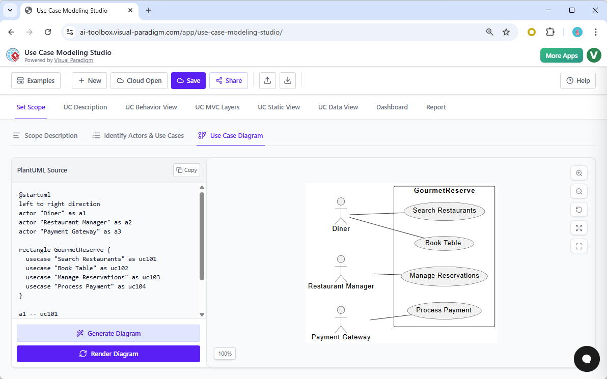
In the landscape of modern software engineering, the bridge between functional requirements and technical implementation is critical. Within the context of the AI-Powered Use Case Modeling Studio, this bridge is constructed through an automated technical design workflow. This process progresses logically from a high-level Use Case Diagram to a detailed Class Diagram, and finally, to a database-centric Entity-Relationship Diagram (ERD).
Understanding this progression is essential for developers and architects who wish to leverage AI to maintain a single source of truth across their documentation and codebases.
The Strategic Value of Use-Case-Scoped Class Diagrams
A common question in architectural modeling is whether a class diagram limited to the scope of a single use case offers value. In the context of this studio, the answer is a definitive yes. Rather than forcing developers to navigate a monolithic system-wide diagram, the system employs a UC Static View. This feature allows the AI to infer domain models directly from the actors, specific use cases, and the detailed “flows of events” provided in the description.
Why Scoping Matters
Generating a class diagram for a specific feature—such as a “Book Table” use case—provides immediate clarity without the noise of the entire application structure. This approach isolates the relevant entities, such as Reservation, Table, and User, allowing for precise architectural mapping.
Advantages of the Scoped Approach
The primary benefit of this workflow is the enhancement of architectural mapping and traceability. By narrowing the focus, the studio bridges the gap between abstract business goals and concrete technical implementation through several key mechanisms:
- MVC Alignment: The studio utilizes UC MVC Layers mapping to translate functional requirements into Model-View-Controller components. A scoped class diagram specifically identifies the “Model” entities (data and logic) required for that unique feature.
- Reduced Complexity: Developers are presented with a clear roadmap for implementation. Instead of deciphering a massive diagram, they receive a targeted visualization of the classes and relationships relevant to the task at hand.
- Dynamic Consistency: The Consistency Engine plays a vital role in maintenance. If a user modifies a use case description—for instance, adding a “party size” attribute to a reservation flow—the engine instantly updates the linked class diagram. This ensures the design documents remain the single source of truth.
- Refined Logic: This granular level of detail allows the AI to apply software design rules effectively, identifying specific attributes and operations necessary to support the logic of the use case.
From Software Objects to Database Structures: Class Diagram to ERD
The transition from the UC Static View (Class Diagram) to the UC Data View (ERD) represents the shift from object-oriented software structures to relational database structures. This transformation is automated to ensure the data layer accurately reflects the functional requirements defined earlier.
Key Transformation Concepts
The process involves a systematic translation of code concepts into data concepts:
| Class Diagram Element | ERD Transformation | Description |
|---|---|---|
| Class | Entity | Classes identified in the static view (e.g., Reservation or MealOrder) become distinct database tables. |
| Attribute | Column | Properties defined within a class (e.g., date, time, party size) are converted into specific data fields or columns within the table. |
| Relationship | Foreign Keys | Associations and compositions in the class diagram are analyzed to establish database relationships, ensuring data integrity. |
This automated synchronization ensures that the database design and application code never drift apart, as both are derived from the same MVC “Model” identified during the initial analysis phase.
The “Kitchen Schematic” Analogy
To visualize the utility of this approach, consider the analogy of building construction. A system-wide diagram is akin to the master blueprint for an entire skyscraper. While essential for the overall structure, it is often too broad for specific trades.
Conversely, the use-case-scoped class diagram acts as a detailed plumbing and electrical schematic specifically for the kitchen. While the skyscraper requires a master plan, the contractor installing the sink needs a localized schematic. They need to know exactly which pipes (data entities) and switches (logic) are required to make the kitchen functional, without being distracted by the wiring of the floors above or below. This focused clarity is exactly what the AI-Powered Use Case Modeling Studio delivers to software developers.