Activity diagrams serve as a fundamental tool for visualizing the dynamic aspects of a system. While sequential flows are intuitive, real-world processes rarely follow a single linear path. To accurately represent complex business logic or system behavior, one must understand how to model parallel processes effectively. This guide explores the mechanics of forking and joining activity flows, ensuring your models reflect true concurrency without introducing ambiguity or logical errors.
Understanding Control Flow vs. Object Flow 🧩
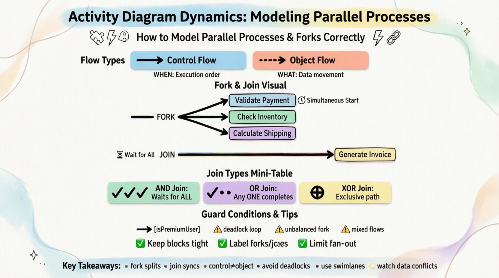
Before diving into parallel structures, it is essential to distinguish between the two primary types of flow found in activity diagrams:
- Control Flow: Represents the order of execution. It dictates when an activity happens based on the completion of a previous one. This is depicted by arrows connecting activity nodes.
- Object Flow: Represents the movement of data or artifacts. It shows what information is passed between activities. This is depicted by dashed lines connecting activity nodes and object nodes.
When modeling parallel processes, we primarily manipulate control flow. The distinction matters because a fork node splits the control, not necessarily the data. Understanding this separation prevents common modeling errors where data dependencies are confused with execution dependencies.
The Fork Node: Splitting the Flow ⚡
A fork node is the mechanism used to initiate parallelism. Visually, it appears as a thick horizontal or vertical bar. It takes exactly one incoming control flow and splits it into multiple outgoing control flows. The critical characteristic of a fork is that all outgoing paths are initiated simultaneously.
Key Characteristics of a Fork
- Single Input: A fork node cannot have multiple incoming control flows. If you need to merge multiple paths before splitting, you must first join them.
- Multiple Outputs: There must be at least two outgoing flows to create a parallel effect.
- Immediate Execution: Upon arrival at the fork, the system does not wait for any path to complete. It triggers all subsequent activities at the same logical moment.
- No Guard Conditions: Typically, guard conditions are placed on the outgoing edges from a fork if specific conditions determine which parallel path activates, though standard forks assume all paths are valid.
Consider a scenario where a user submits a request. The system must validate the input, check inventory, and calculate shipping costs simultaneously. Using a fork node allows these three activities to run in parallel rather than waiting for validation to finish before checking inventory.
The Join Node: Synchronizing the Flow 🔗
If a fork splits the work, a join node brings it back together. A join node is also depicted as a thick bar, but it functions inversely to the fork. It takes multiple incoming control flows and merges them into a single outgoing control flow.
Key Characteristics of a Join
- Multiple Inputs: A join node requires two or more incoming flows to be active.
- Single Output: Once the join condition is met, only one flow continues to the next activity.
- Synchronization: The join node acts as a barrier. The process cannot proceed past the join until all incoming paths have completed their respective activities.
This synchronization is crucial. If one parallel path takes significantly longer than the others, the system waits at the join node. This ensures that subsequent steps do not begin until all necessary parallel tasks are finished.
Types of Join Semantics 🧮
Not all joins function identically. Depending on the logic of your system, you may need different types of join behavior. Standard UML activity diagrams default to an AND Join, but understanding alternatives helps in modeling complex logic.
| Join Type | Behavior | Use Case |
|---|---|---|
| AND Join | Waits for all incoming flows to complete. | Standard synchronization where every task must finish. |
| OR Join | Proceeds when any single incoming flow completes. | Optional paths where the next step triggers if one task finishes first. |
| XOR Join | Proceeds based on specific conditions or signals. | Exclusive paths where only one parallel branch is active. |
For most standard workflow modeling, the AND Join is the default expectation. However, if you are modeling a system where a backup process should only trigger if the primary fails, you might utilize a conditional join logic or structure the diagram to reflect exclusive paths prior to the join.
Guard Conditions and Branching 🚦
Parallel processes often require conditional logic. You might need to determine which parallel path to activate based on data values. This is achieved using guard conditions placed on the edges leaving the fork or preceding the fork.
Implementing Guard Conditions
- Format: Conditions are written in square brackets, e.g., [isPremiumUser].
- Placement: They appear on the arrow connecting the fork to the subsequent activity.
- Logic: If the condition evaluates to true, the control flow traverses that edge. If false, it does not.
It is important to note that guard conditions on a fork do not guarantee that all paths will execute. They determine which parallel branches are active. If you have a fork with three outgoing paths and two conditions evaluate to false, only one path will execute. The join node will then wait for that single path to complete, potentially causing confusion if the modeler assumes all paths were intended to run.
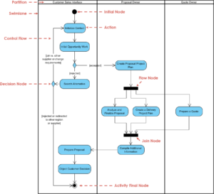
Scenario Walkthrough: Order Fulfillment Process 📦
To visualize these concepts, let us examine a detailed order fulfillment process. This scenario demonstrates how to structure parallel activities for efficiency while maintaining data integrity.
Step 1: Receive Order
The process begins when an order is submitted. This is a single activity node. Once completed, the flow moves to a decision node to validate the order details.
Step 2: Validation Fork
Upon validation, the control flow reaches a fork node. This is where the process splits into parallel tracks to optimize time.
- Track A: Validate Payment Method.
- Track B: Check Inventory Availability.
- Track C: Calculate Estimated Delivery Date.
These three activities occur simultaneously. The system does not wait for payment validation to finish before checking inventory.
Step 3: The Join Point
After all three tracks complete, they converge at a join node. This node ensures that:
- Payment was approved.
- Items are in stock.
- A delivery date is confirmed.
Only when all three conditions are met does the flow proceed to the next stage. If inventory is low, Track B might fail or return a specific signal, which the join node handles by preventing the order from moving forward.
Step 4: Final Processing
Once the join is passed, the system generates the invoice and initiates the shipping workflow. This sequential step follows the parallel block, ensuring all prerequisites are satisfied.
Common Modeling Pitfalls ⚠️
Modeling concurrency is error-prone. Even experienced architects can introduce logical flaws that render a diagram unusable for developers or stakeholders. Below are common mistakes to avoid.
1. The Deadlock Scenario
A deadlock occurs when two or more processes are waiting for each other to release resources, resulting in a system that never completes. In activity diagrams, this often happens when a join node is placed incorrectly.
- The Error: Creating a loop where a join waits for a fork that depends on the join.
- The Fix: Ensure there is a clear termination point. Every parallel branch must eventually reach a join or an end node.
2. Improper Join Semantics
Using a join that waits for all paths when only one is required creates unnecessary latency. Conversely, using a join that proceeds on any path when all are required creates a race condition risk.
- The Error: Joining optional paths with an AND join.
- The Fix: Clearly define whether a parallel path is mandatory. Use decision nodes to filter optional paths before the join if necessary.
3. Mixing Control and Object Flow
Confusing the flow of control with the flow of data leads to incorrect execution logic.
- The Error: Drawing a control arrow where an object flow is needed, or vice versa.
- The Fix: Use dashed lines for data movement and solid lines for execution order. Ensure object nodes are connected to the activities that produce or consume them.
4. Unbalanced Forks and Joins
While not strictly forbidden, having multiple forks without corresponding joins creates „orphaned“ parallel threads. These threads end at an activity node but never merge back into the main flow.
- The Error: Forking into three paths, but one path ends while the other two join.
- The Fix: Ensure every fork has a corresponding join, or explicitly mark the end of the specific parallel branch with an Activity Final Node.
Best Practices for Clean Models 🛡️
To maintain clarity and usability, adhere to these standards when constructing activity diagrams involving parallel processes.
- Keep Parallel Blocks Tight: Do not spread parallel activities across the entire diagram. Keep related parallel tasks close together to reduce visual clutter.
- Use Swimlanes: If the parallel processes belong to different departments or system components, use swimlanes. This clarifies responsibility alongside concurrency.
- Label Forks and Joins: Add labels like „Fork: Start Parallel“ or „Join: Wait for All“ to make the intent explicit, especially in complex diagrams.
- Limit Fan-Out: Avoid creating forks with too many outgoing paths (e.g., more than four). If you have many parallel tasks, consider grouping them into a sub-process or using a composite activity.
- Document Guard Conditions: If guard conditions are complex, document the logic outside the diagram or use clear, descriptive text on the edges.
Integrating Data with Control Flow 💾
Parallel processes often manipulate shared data. In a real system, if two parallel threads try to write to the same database record simultaneously, a race condition occurs. Activity diagrams do not inherently enforce data locking, but they should reflect the logical dependencies.
Object Nodes in Parallel
- Read-Only: If parallel activities only read data, no conflict exists. The diagram can simply show object flows entering both parallel paths.
- Write-Write: If parallel activities write to the same object, you must model a synchronization mechanism. This often involves a separate „Lock“ activity or a database transaction block within one of the paths.
- Read-Write: If one path reads and another writes, the order of execution matters. Use a decision node or a specific activity sequence to ensure the read happens before the write, or use a join to synchronize the update.
Refining the Diagram for Stakeholders 📝
Finally, remember that the audience for the diagram dictates the level of detail. Technical developers need to see the exact fork and join semantics. Business stakeholders may only need to see that „Payment and Inventory check happen at the same time.“
- For Developers: Use precise fork/join bars and explicit control flow arrows. Ensure object flows are connected to data stores.
- For Management: Abstract complex joins. You might represent the parallel block as a single „Validation Phase“ node with a note indicating internal concurrency.
By focusing on the logical intent of the fork and join, you ensure the diagram serves its purpose: communication and specification. Whether the goal is to identify bottlenecks or define system architecture, accurate modeling of parallel processes is the cornerstone of reliable system design.
Summary of Key Takeaways 🎯
- Fork nodes split control flow into simultaneous paths.
- Join nodes synchronize multiple paths, waiting for all inputs by default.
- Distinguish clearly between control flow (execution order) and object flow (data movement).
- Avoid deadlocks by ensuring all parallel paths have a defined termination.
- Use swimlanes to clarify ownership of parallel tasks.
- Consider data conflicts when multiple paths access the same information.
Mastering these dynamics allows for the creation of robust, scalable models that accurately reflect the complexity of modern systems. Focus on the logic, respect the synchronization points, and your activity diagrams will provide a clear blueprint for implementation.