Effective system analysis begins with a clear understanding of what needs to be built. Without precise requirements, projects drift into ambiguity, leading to costly rework and misaligned expectations. Unified Modeling Language (UML) offers a standardized visual language to bridge the gap between stakeholder needs and technical specifications. This guide explores how system analysts can leverage UML diagrams to capture, analyze, and validate requirements efficiently.
🏗️ Why UML Matters in Requirements Engineering
Requirements gathering is not merely about writing down a list of features. It is about understanding the context, the actors, the data flows, and the behavioral logic of a system. Text alone often fails to capture complex interactions or temporal sequences. Visual models provide a shared vocabulary that reduces misinterpretation.
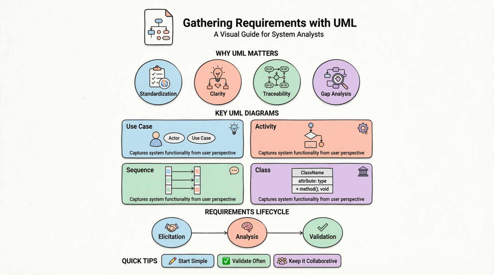
Using UML for requirements serves several critical functions:
- Standardization: UML provides a consistent notation understood by developers, testers, and business stakeholders.
- Clarity: Diagrams simplify complex logic into visual representations that are easier to digest.
- Traceability: Models can be linked to specific requirement IDs, ensuring every piece of code stems from a defined need.
- Gap Analysis: Visualizing the system often reveals missing steps or logical contradictions early in the process.
🗺️ Key UML Diagrams for Requirement Modeling
Not every diagram serves the same purpose. Selecting the right visual tool depends on the type of requirement being captured. Below are the primary diagrams utilized during the requirements phase.
1. Use Case Diagrams 🧩
Use Case diagrams are the cornerstone of functional requirement modeling. They depict the interactions between external actors (users, systems, or devices) and the system itself.
- Actors: Represented as stick figures. These are the roles interacting with the system, such as „Administrator“ or „Customer“.
- Use Cases: Represented as ovals. Each oval represents a specific goal or function the actor wants to achieve.
- Relationships: Lines connect actors to use cases. Relationships like „Include“ and „Extend“ help manage complexity and reuse common behaviors.
When to use: Best for high-level functional requirements. It answers the question: „Who can do what?“
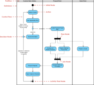
2. Activity Diagrams ⚙️
Activity diagrams describe the flow of control from activity to activity. They are essentially flowcharts enhanced with UML notation. These diagrams are crucial for understanding business processes and workflow logic.
- Swimlanes: Divide activities by responsible party (e.g., User vs. System).
- Forks and Joins: Represent parallel processing or convergence of paths.
- Decision Nodes: Diamond shapes indicating branching logic based on conditions.
When to use: Ideal for detailed workflow requirements, approval processes, and algorithmic logic.
3. Sequence Diagrams 💬
Sequence diagrams focus on the interaction between objects over time. They show the order of messages exchanged to accomplish a specific use case.
- Lifelines: Vertical dashed lines representing objects or actors.
- Messages: Horizontal arrows showing data or calls passed between lifelines.
- Activation Bars: Rectangles on lifelines indicating when an object is actively processing a message.
When to use: Essential for defining interaction logic, API contracts, and timing constraints.
4. Class Diagrams 🏛️
While often associated with design, Class diagrams are vital for data requirements. They define the static structure of the system, including entities, attributes, and relationships.
- Attributes: Data fields associated with an entity.
- Methods: Operations available on an entity.
- Associations: Links between classes indicating relationships (e.g., One-to-Many).
When to use: Necessary for database schema planning and data integrity rules.
🔄 The Requirements Lifecycle with UML
Modeling is not a one-time event. It is an iterative process that evolves as understanding deepens. The workflow generally follows these stages:
Elicitation 🤝
During this phase, analysts gather raw information from stakeholders. UML tools are not used yet. Instead, interviews, workshops, and document reviews occur. The goal is to collect the „What“ without the „How“.
Analysis 🧠
Here, raw information is structured. Analysts identify the core actors and the primary goals. Use Case diagrams are drafted to outline the scope. Activity diagrams begin to map out the specific steps for high-priority processes.
Validation ✅
Models are presented back to stakeholders for verification. Does the diagram accurately reflect their mental model? Are any steps missing? This feedback loop ensures the requirements are complete and correct before development begins.
📊 Choosing the Right Diagram: A Comparison
Selecting the correct modeling artifact prevents confusion. Use the table below to determine which diagram suits specific requirement types.
| Diagram Type | Focus | Best For | Complexity Level |
|---|---|---|---|
| Use Case | Functional Goals | High-level feature listing | Low |
| Activity | Workflow Logic | Business process flows | Medium |
| Sequence | Interaction Timing | API calls and message flow | High |
| Class | Data Structure | Database design and entities | High |
| State Machine | Object Lifecycle | Complex state transitions (e.g., Order Status) | Medium |
🚧 Common Pitfalls to Avoid ⚠️
Even experienced analysts make mistakes when modeling requirements. Being aware of common traps helps maintain quality.
- Over-Modeling: Creating diagrams for every minor requirement creates noise. Focus on the critical paths and high-value features first.
- Ignoring Non-Functional Requirements: UML primarily models behavior and structure. Performance, security, and reliability constraints must be documented separately in text or special tags.
- Assuming Technical Knowledge: Stakeholders may not understand UML notation. Keep diagrams simple and explain symbols during reviews.
- Static Snapshots: Requirements change. Models should be versioned and updated to reflect the current understanding of the system.
- Lack of Traceability: If a diagram element cannot be traced back to a business need, it is likely unnecessary technical debt.
🤝 Facilitating Collaboration 👥
UML is a communication tool, not just a documentation tool. The value comes from the discussions it sparks. When presenting a diagram:
- Walk Through Scenarios: Don’t just show the diagram. Walk through a specific user journey step-by-step using the visual elements.
- Encourage Questions: Ask stakeholders, „What happens if the user cancels at this step?“ This often reveals missing exception paths.
- Keep it Accessible: Use whiteboards or digital collaboration tools that allow everyone to view the model simultaneously without installing specific software.
- Iterate Quickly: Draw rough sketches first. Refine the notation only after the logic is agreed upon.
🔮 Maintaining Requirement Traceability 📎
As the project grows, keeping track of which requirement maps to which model element is vital. A traceability matrix helps link requirements to design artifacts.
Consider the following workflow for traceability:
- Assign IDs: Give every requirement a unique identifier (e.g., REQ-001).
- Link to Models: Annotate diagram elements with the corresponding requirement ID.
- Verify Coverage: Ensure every requirement has at least one visual representation.
- Monitor Changes: When a requirement changes, update the model and verify the impact on other linked elements.
📝 Final Thoughts on Structured Analysis 🧾
Mastering UML for requirements is a skill that develops over time. It requires balancing technical precision with business clarity. By focusing on the right diagrams for the right context, analysts can create models that serve as blueprints for successful delivery.
Remember that the goal is not to create beautiful diagrams, but to create accurate representations of reality. Start simple, validate frequently, and adapt as the project evolves. This disciplined approach reduces risk and ensures the final system aligns with the intended business value.
As you move forward, consider integrating these models into your project management workflow. They should live alongside user stories and technical specifications, forming a cohesive documentation ecosystem that guides the entire development lifecycle.