System modeling relies on precision. When a diagram depicts a relationship that does not exist in reality, it introduces risk. These errors are often described as hallucinations in the context of automated or semi-automated design processes. A false interaction suggests that Object A sends a message to Object B, when in the actual system architecture, that path is blocked or non-existent. This guide focuses on identifying and eliminating these inaccuracies within Communication Diagrams to ensure your system design remains a reliable blueprint.
📐 Understanding the Role of Communication Diagrams
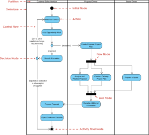
A Communication Diagram (often associated with UML) visualizes the interactions between objects or components in a specific scenario. Unlike sequence diagrams which emphasize time, communication diagrams emphasize the structural relationships and the flow of data between entities. They are vital for understanding how parts of a system collaborate to achieve a function.
When these diagrams contain hallucinations—spurious links or messages that imply functionality not present in the code—they become misleading artifacts. The goal is not merely to draw lines, but to verify truth. Every arrow drawn must correspond to a method call, an event listener, or a data transmission that actually occurs during runtime.
🚨 Defining False Interactions
A false interaction occurs when the model depicts a connection that is logically impossible or technically unsupported. These can be categorized into several distinct types:
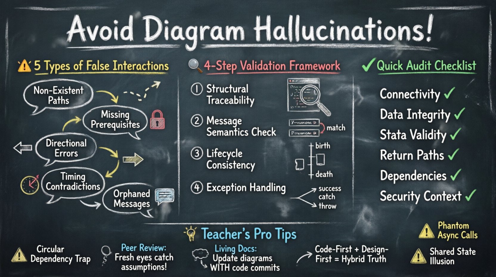
- Non-Existent Paths: An arrow connects two components that are not directly linked in the network topology or object graph.
- Missing Prerequisites: A message is shown being sent without the necessary state or authentication context established beforehand.
- Directional Errors: Data flows are depicted in the wrong direction, implying a sender role for a consumer or vice versa.
- Timing Contradictions: Asynchronous messages are treated as synchronous, or return messages appear before the request completes.
- Orphaned Messages: A message is sent, but no object in the diagram has a defined responsibility to receive it.
Each of these categories introduces ambiguity. Developers reading the diagram may implement code that is dead on arrival, leading to technical debt and debugging nightmares.
🔍 Root Causes of Diagrammatic Errors
Why do these inaccuracies happen? Understanding the source is the first step toward prevention. Errors usually stem from assumptions rather than observation.
1. Assumption of Connectivity
It is common to assume that because two objects exist in the same system, they can talk to each other directly. In a microservices architecture, for instance, service A cannot simply talk to service B without a gateway or API layer. Drawing a direct line without this intermediate step creates a false interaction.
2. Oversimplified State Management
Diagrams often show a successful flow (Happy Path) without depicting the state changes required to enable that flow. If Object A needs a token from Object B before calling Object C, but the diagram shows A calling C directly, the interaction is hallucinated.
3. Template Reliance
When creating diagrams, teams often reuse templates from previous projects. A template might include a “Database Write” node that is not actually required for the specific feature being modeled. Copying this node without verification introduces a phantom dependency.
4. Automated Generation Drift
In environments using AI or code-to-diagram tools, the model can drift from the codebase. If the code changes but the diagram generation logic is not re-run or reviewed, the diagram retains old interactions. These are the digital equivalent of ghosts.
🛠️ A Framework for Validation
To eliminate false interactions, a systematic validation process is required. This process should be applied before the diagram is considered final or shared with the development team.
Step 1: Structural Traceability
For every object in the diagram, verify that it exists in the codebase. If you draw a “PaymentService” class, ensure that file or module exists. Then, verify the links. Does the “PaymentService” actually have a dependency on the “UserRepository”? Check the dependency graph.
Step 2: Message Semantics Check
Examine every arrow. Does the method name match the signature? If the diagram shows a method named calculateTotal, does that method exist? Does it accept the parameters shown in the message label? Mismatches here are often overlooked but critical.
Step 3: Lifecycle Consistency
Objects have lifecycles. They are created, used, and destroyed. A communication diagram often implies that objects are available. Ensure that the interaction does not require an object to exist before it is instantiated. For example, you cannot send a message to a database connection object before the connection pool has initialized it.
Step 4: Exception Handling Verification
Most diagrams focus on success. However, false interactions often hide in the error paths. If an API call fails, does the diagram show a fallback? If the diagram implies a retry mechanism that is not coded, that is a hallucination. Ensure error paths are as rigorously checked as success paths.
✅ Validation Checklist
Use this table to audit your diagrams before release. Each row represents a critical check to prevent specific types of false interactions.
| Check Category | Validation Criteria | Risk if Ignored |
|---|---|---|
| Connectivity | Are all linked objects physically connected in the architecture? | Network errors, unreachable endpoints |
| Data Integrity | Do input parameters match the receiving method signature? | Runtime exceptions, type mismatches |
| State Validity | Is the object in a valid state to receive the message? | Null pointer errors, invalid state crashes |
| Return Paths | Is there a defined response or acknowledgment for every request? | Timeouts, hanging processes |
| Dependency Existence | Does every dependency actually exist in the repository? | Build failures, missing modules |
| Security Context | Are authentication or authorization steps shown where required? | Security vulnerabilities, access denied |
🤝 The Human Element in Verification
Automation helps, but human oversight is irreplaceable. A diagram is a contract between the design team and the implementation team. If the designer assumes a capability that the developer does not have, the communication fails.
Peer Review Cycles
Implement a mandatory review step where a colleague who did not create the diagram examines it. Fresh eyes are better at spotting assumptions. Ask the reviewer: “Where would this break?” rather than “Does this look good?”.
Code-First vs. Design-First
Be careful with the order of operations. If you design first, you risk building a dream system. If you code first, you risk missing the big picture. The most accurate diagrams often come from a hybrid approach: sketch the flow, code the core, then update the diagram to reflect reality.
Living Documentation
A diagram that sits on a server for months becomes a lie. Treat the diagram as code. If the code changes, the diagram must be updated in the same commit or pull request. This ensures the diagram remains a source of truth rather than a historical artifact.
⚠️ Specific Scenarios for False Interactions
Certain patterns are notorious for generating false interactions. Recognizing these patterns allows for targeted prevention.
1. The Circular Dependency Trap
Object A calls Object B, and Object B calls Object A. In a diagram, this looks like a loop. In reality, this causes a stack overflow or a deadlock. While sometimes necessary in specific designs, it must be explicitly managed. If the diagram shows a loop without indicating a termination condition, it is a hallucination of infinite recursion.
2. The Phantom Asynchronous Call
Showing an async call without an async callback handler. If Object A fires a message and expects a return, but the architecture is fire-and-forget, the diagram misrepresents the control flow. The developer might wait for a response that never comes.
3. The Shared State Illusion
Multiple objects drawing lines to a central data store implies shared state. In a distributed system, objects might have local caches that are not synchronized. If the diagram implies global consistency where only eventual consistency exists, the interaction is false.
4. The Interface Mismatch
Object A implements Interface X. Object B expects Interface Y. The diagram draws a line between them. This is a classic compilation error waiting to happen. The interface contract must be explicit in the diagram, not assumed.
🔄 Iterative Refinement Process
Prevention is not a one-time event. It is a cycle of refinement. Start with a high-level view, then drill down into specifics, validating at each level.
- Level 1: Context. Who is the user? What is the high-level goal?
- Level 2: Components. What services are involved?
- Level 3: Messages. What data is passed?
- Level 4: Data Structures. What do the objects look like?
At each level, ask: “Is this interaction real?” If you cannot answer with evidence from the code or requirements, remove the interaction. It is better to have an incomplete diagram than an inaccurate one.
📉 The Cost of Inaccuracy
Why spend the effort? The cost of a false interaction is measured in wasted development time. When a developer follows a diagram and hits a dead end, they must stop, investigate, and correct the design. This breaks flow and increases project timelines.
Beyond time, there is the cost of reliability. If a diagram implies a feature that handles a specific error case, but that code path is never tested because it was only in the diagram, bugs will appear in production. These bugs are harder to fix because the logic was never verified during the design phase.
🧩 Maintaining Diagram Integrity
Once the diagram is accurate, it must stay that way. Maintenance is the final phase of prevention.
- Version Control: Store diagrams alongside code. Use branches for design changes.
- Change Logs: Document why an interaction was removed or added. Context is crucial for future reviewers.
- Automated Checks: If possible, use tools that lint the diagram against the codebase. While you cannot rely on software alone, these tools can highlight obvious discrepancies.
🎯 Summary of Best Practices
To ensure your Communication Diagrams are free of hallucinations, adhere to these core principles:
- Verify every link against the actual system architecture.
- Ensure every message has a valid receiver and sender.
- Validate state prerequisites before message flow.
- Include error paths, not just success paths.
- Update diagrams whenever the code changes.
- Involve multiple reviewers to catch assumptions.
- Treat the diagram as a contract, not a suggestion.
By treating diagramming as a rigorous engineering task rather than a sketching exercise, you eliminate the risk of false interactions. Your designs will remain faithful to the system, providing a stable foundation for development and maintenance.