
Designing a distributed system requires precision, foresight, and clear communication. As software complexity grows, the need for standardized modeling becomes critical. Unified Modeling Language, or UML, serves as a blueprint for these intricate structures. It provides a common visual language for architects, developers, and stakeholders to understand how microservices interact, scale, and evolve.
Microservices architecture breaks applications into small, independent services. While this offers agility, it introduces significant operational challenges. Without proper documentation and design artifacts, the system can quickly become a tangled web of dependencies. UML offers the structure needed to navigate this complexity. This guide explores how modeling techniques apply specifically to service-oriented design.
🧩 Why Modeling Matters in Distributed Systems
Building microservices is not just about coding. It is about defining boundaries, contracts, and data flows. When multiple teams work on different services, ambiguity leads to integration failures. Visual models bridge this gap.
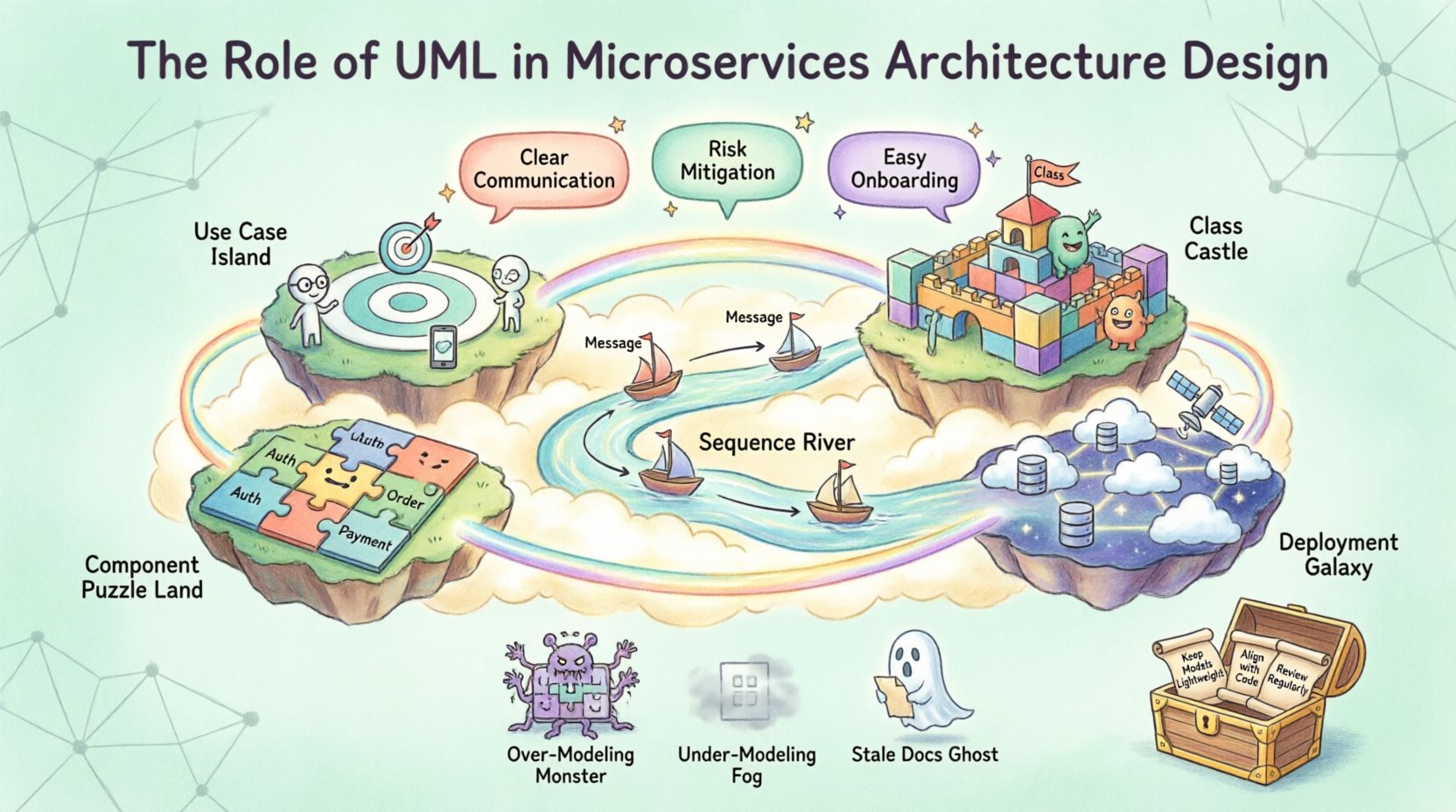
- Communication: Diagrams provide a single source of truth for cross-functional teams.
- Abstraction: They allow architects to focus on high-level logic without getting lost in implementation details.
- Risk Mitigation: Identifying bottlenecks or single points of failure before code is written.
- Onboarding: New engineers can understand the system landscape faster through visual representations.
Unlike monolithic applications, microservices rely heavily on network communication. Understanding these interactions is paramount. Static diagrams show structure, while dynamic diagrams show behavior. Combining both creates a holistic view of the ecosystem.
📊 Key UML Diagrams for Microservices
Different stages of development require different views. Using the right diagram type ensures clarity. Below is a breakdown of the most relevant UML diagrams for this architecture.
1️⃣ Use Case Diagrams 🎯
Use case diagrams map out the functional requirements from the perspective of external actors. In a microservices context, actors can be users, third-party APIs, or internal administrative systems.
- Identify which service handles specific user actions.
- Define the scope of each service.
- Highlight external dependencies early.
This diagram helps in determining service boundaries. If a use case touches too many services, it may indicate a need for refactoring or a new orchestrating layer.
2️⃣ Class Diagrams 🏗️
Class diagrams describe the static structure within a service. While microservices hide internal implementation details, internal class structures matter for maintainability.
- Define entities, value objects, and aggregates.
- Clarify relationships like inheritance or association.
- Document database schemas and data models.
For domain-driven design, these diagrams align with bounded contexts. They ensure that the internal logic of a service remains cohesive and does not leak into others.
3️⃣ Sequence Diagrams ⏳
Sequence diagrams are perhaps the most critical for microservices. They visualize the flow of messages between services over time.
- Show synchronous vs. asynchronous calls.
- Identify request chains and response handling.
- Highlight error scenarios and timeouts.
When designing an API gateway, sequence diagrams help map how a single user request triggers multiple downstream service calls. This prevents race conditions and data inconsistencies.
4️⃣ Component Diagrams 🧱
Component diagrams group related classes into modules or services. They show the high-level composition of the system.
- Visualize the deployment units.
- Show interfaces and provided/required capabilities.
- Illustrate how services depend on external libraries or databases.
This view is essential for understanding coupling. It helps architects decide if a component should be moved to a different service to reduce network overhead.
5️⃣ Deployment Diagrams 🌐
Deployment diagrams map the physical architecture. They show nodes, containers, and network topology.
- Define server configurations and hosting environments.
- Illustrate load balancers and proxy layers.
- Show database replication and storage locations.
In cloud-native environments, this diagram evolves to include container orchestration nodes. It ensures that the physical infrastructure supports the logical design.
| Diagram Type | Primary Focus | Best Used For |
|---|---|---|
| Use Case | Functional Requirements | Stakeholder Alignment |
| Class | Internal Structure | Data Modeling & Logic |
| Sequence | Interaction Flow | API Contracts & Integration |
| Component | System Composition | Service Boundaries |
| Deployment | Infrastructure | DevOps & Scaling |
🔗 Domain-Driven Design and UML
Domain-Driven Design (DDD) pairs naturally with UML modeling. DDD emphasizes understanding the business domain to shape the software structure. UML provides the notation to express these domains.
Bounded Contexts
A bounded context is a logical boundary within which a specific model applies. In UML, these can be represented as distinct packages or subsystems.
- Ensure each microservice maps to a single bounded context.
- Use component diagrams to show context boundaries clearly.
- Document translation layers where contexts interact.
This approach prevents context pollution. If one service tries to use the domain model of another, it creates tight coupling. UML helps visualize these boundaries explicitly.
Ubiquitous Language
DDD promotes a shared vocabulary. UML diagrams serve as a visual representation of this language.
- Names in diagrams should match business terminology.
- Relationships should reflect real-world domain rules.
- Avoid technical jargon that confuses business stakeholders.
When the diagram matches the language, communication improves. Developers and business owners can discuss the system using the same terms found in the visual models.
🛠️ Designing APIs and Contracts
Microservices communicate via APIs. Defining these contracts is a critical part of the design phase. While UML is not primarily an API definition language, it complements specifications.
Interface Modeling
Use class diagrams to define the data structures passed between services. Define request and response objects clearly.
- Specify required fields and optional fields.
- Document data types and validation rules.
- Outline error response structures.
This reduces integration friction. When a service consumer knows exactly what to expect, development speeds up. It also aids in versioning strategies.
Interaction Patterns
Sequence diagrams help choose the right interaction pattern.
- Request-Response: Synchronous calls for immediate feedback.
- Event-Driven: Asynchronous messaging for decoupling.
- Orchestration: A central service coordinates the flow.
- Choreography: Services react to events without a central controller.
Each pattern has trade-offs. UML helps simulate these flows to understand latency and failure points before deployment.
⚠️ Common Pitfalls in Modeling
Even with the right tools, mistakes happen. Understanding common errors helps avoid them.
Over-Modeling
Creating diagrams that are too detailed can slow down development. A diagram should explain the concept, not every line of code.
- Focus on boundaries and flows, not internal logic.
- Update models only when architecture changes significantly.
- Use high-level views for stakeholder meetings.
Under-Modeling
Conversely, skipping diagrams leads to confusion. Essential interactions may be missed.
- Document critical data flows explicitly.
- Ensure security boundaries are clear.
- Map out failure scenarios and recovery paths.
Stale Documentation
A model that does not match the code is worse than no model. It creates false confidence.
- Integrate modeling into the CI/CD pipeline.
- Update diagrams as part of the code review process.
- Automate diagram generation where possible.
🔄 Maintenance and Evolution
Microservices evolve constantly. New features are added, and old ones are retired. The modeling process must support this agility.
Version Control for Models
Treat diagrams as code. Store them in the same repository as the application source.
- Track changes over time.
- Review model diffs alongside code diffs.
- Ensure historical versions are accessible for debugging.
Refactoring Strategies
When refactoring a service, update the diagrams first. This ensures the intent is preserved.
- Visualize the ‘To-Be’ state before coding.
- Check for unintended side effects on dependent services.
- Validate that new boundaries align with business needs.
🚀 Future Trends and Considerations
The landscape of architecture is shifting. Cloud-native technologies and serverless computing introduce new modeling challenges.
Serverless Integration
Function-as-a-Service models change how components are grouped. UML must adapt to show event triggers and stateless execution.
- Model triggers and event sources explicitly.
- Focus on state management across function invocations.
- Consider cold start impacts in sequence diagrams.
Service Mesh
Infrastructure layers like service meshes handle traffic management. Deployment diagrams need to reflect this offloading.
- Show sidecar proxies in the deployment view.
- Document traffic policies and security rules.
- Visualize observability data flows.
📝 Best Practices Summary
To get the most out of UML in microservices, follow these core principles.
- Start Simple: Begin with high-level component diagrams.
- Focus on Flow: Use sequence diagrams to validate integrations.
- Keep it Updated: Treat models as living documents.
- Collaborate: Use diagrams as discussion tools, not just deliverables.
- Standardize: Agree on notation conventions across teams.
Consistency in notation prevents confusion. If one team uses a specific symbol for a database, all teams should use it.
🎯 Conclusion
UML remains a powerful asset in the microservices era. It brings order to distributed chaos. By visualizing boundaries, flows, and structures, teams can build systems that are robust and maintainable. The key lies in balancing detail with agility. Models should guide development, not hinder it.
As systems grow, the need for clear architectural communication increases. Investing time in proper modeling pays dividends in reduced technical debt and faster delivery. Whether designing the next generation of cloud applications or refactoring legacy systems, UML provides the clarity needed to succeed.
Remember that the goal is not perfection. It is understanding. Use these tools to facilitate conversation and alignment. When the team agrees on the design, the implementation follows naturally.