
Activity diagrams are a cornerstone of system modeling and software engineering. They provide a visual representation of the dynamic aspects of a system, illustrating the flow of control and data from one activity to another. When creating these diagrams, adherence to the Unified Modeling Language (UML) standards is crucial. A non-compliant diagram can lead to misinterpretation by stakeholders, development errors, and difficulties in maintenance. This guide provides a rigorous checklist of 15 points to verify your activity diagrams meet industry standards.
Whether you are designing a complex workflow, defining business processes, or modeling system logic, following a structured approach ensures clarity and precision. This checklist covers the essential elements, from the initial state to the final termination, ensuring that your model communicates intent accurately without ambiguity.
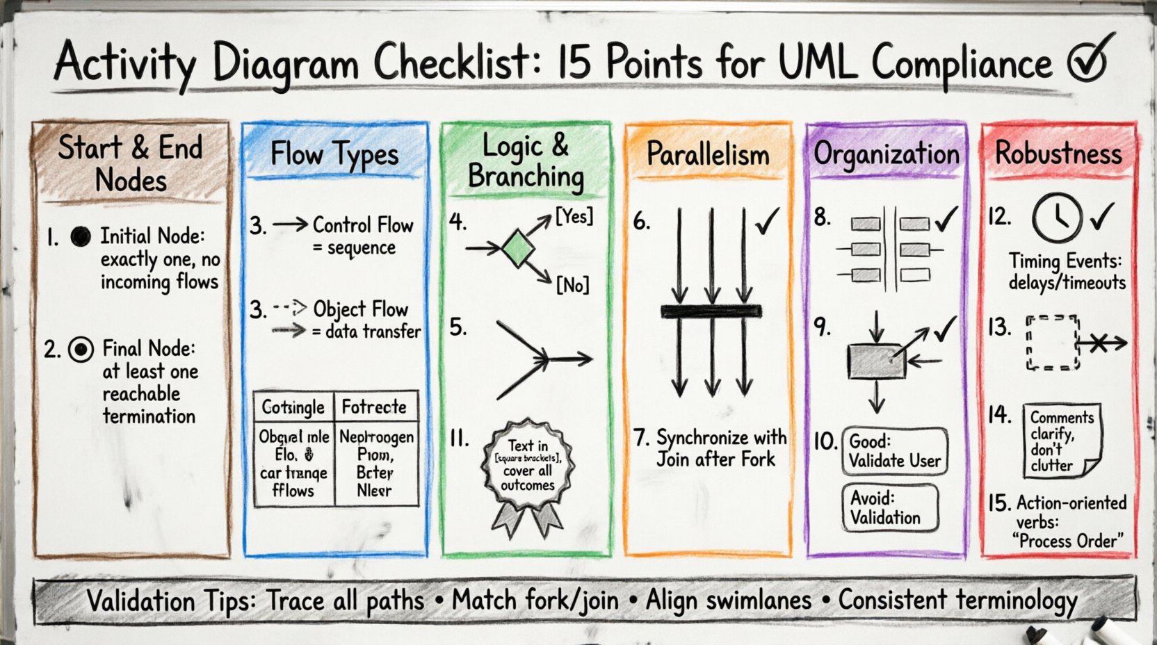
The 15-Point Compliance Checklist ✅
To ensure your activity diagram is robust and standard-compliant, review the following 15 points. Each item addresses a specific component or rule defined in the UML specification.
1. Initial Node Presence and Placement 🟤
- Requirement: Every activity diagram must have exactly one initial node.
- Visual Standard: Represented as a solid black circle.
- Check: Ensure there are no incoming flows to this node. It is the singular entry point for the process.
- Pitfall: Multiple start nodes can imply parallel entry points that are not intended, leading to confusion about the process trigger.
2. Final Node Configuration ⏹️
- Requirement: The diagram must define how the process terminates.
- Visual Standard: Represented as a bullseye symbol (a black circle inside a larger black ring).
- Check: Ensure there is at least one final node reachable from the start node. It is not strictly required to have only one, but flow must converge to termination points.
- Pitfall: Leaving a flow without a termination point suggests an infinite loop or an incomplete process.
3. Control Flow vs. Object Flow Distinction 🔄
- Requirement: Clearly distinguish between the movement of control and the movement of data.
- Visual Standard: Control flow uses solid lines with arrowheads. Object flow uses dashed lines with open arrowheads.
- Check: Review every edge to determine if it represents a signal to proceed (control) or a data artifact (object).
- Pitfall: Mixing these flows without distinction makes the diagram difficult to read and violates UML syntax.
4. Decision Node Logic ⚖️
- Requirement: Decision nodes must manage branching logic correctly.
- Visual Standard: A diamond shape with one incoming flow and multiple outgoing flows.
- Check: Every outgoing edge from a decision node must have a guard condition labeled (e.g., [Yes], [No]).
- Pitfall: Unlabeled edges create ambiguity regarding which path is taken under specific conditions.
5. Merge Node Usage 🤝
- Requirement: Use merge nodes where decision paths converge.
- Visual Standard: Similar to a decision node but with multiple incoming flows and one outgoing flow.
- Check: Ensure merge nodes do not combine incompatible flows. They simply unify control paths.
- Pitfall: Using a merge node where a join node is required can lead to logic errors regarding concurrency.
6. Join Node Synchronization 🔗
- Requirement: Join nodes synchronize parallel threads of execution.
- Visual Standard: A thick horizontal bar.
- Check: Ensure that all incoming flows to a join node are active before the outgoing flow proceeds.
- Pitfall: Failing to use a join node after a fork node implies that the parallel paths are not synchronized, potentially causing race conditions in the logic.
7. Fork Node Parallelism ➡️
- Requirement: Fork nodes split a single flow into multiple concurrent paths.
- Visual Standard: A thick horizontal bar perpendicular to the flow direction.
- Check: Verify that the fork node has exactly one incoming flow and multiple outgoing flows.
- Pitfall: Creating parallel paths without a subsequent join node leaves the diagram open-ended regarding state synchronization.
8. Swimlanes (Partitions) for Responsibility 🏊
- Requirement: Use swimlanes to assign activities to specific actors or systems.
- Visual Standard: Rectangular boxes containing activities, with the actor name at the top.
- Check: Ensure every activity is assigned to a swimlane. Unassigned activities create ambiguity about ownership.
- Pitfall: Crossing swimlanes frequently without clear handoff points can obscure the flow of responsibility between departments.
9. Object Node Representation 📦
- Requirement: Objects created, modified, or consumed must be explicitly shown.
- Visual Standard: A rectangle with a folded corner.
- Check: Verify that object flows connect to object nodes or activities appropriately.
- Pitfall: Ignoring object nodes can result in a model that describes control but fails to capture data dependencies.
10. Activity State Granularity 🎯
- Requirement: Activities should be atomic or decomposable units of work.
- Visual Standard: Rounded rectangles.
- Check: Ensure activities are not too granular (too many nodes) or too coarse (too much detail inside one box).
- Pitfall: Over-complicating the diagram with excessive detail makes it unreadable. Under-specifying it fails to guide implementation.
11. Guard Conditions Clarity 🏷️
- Requirement: Conditions on flows must be unambiguous.
- Visual Standard: Text enclosed in square brackets on the edge.
- Check: Review all guard conditions for logical completeness. Do the conditions cover all possible outcomes?
- Pitfall: Missing a condition can imply a default path that does not exist in the actual logic.
12. Timing Events ⏱️
- Requirement: Use timing events to represent delays or timeouts.
- Visual Standard: A clock symbol or text indicating duration.
- Check: Ensure timing events are used where duration is critical to the process flow.
- Pitfall: Omitting timing constraints can lead to assumptions about execution speed that do not match reality.
13. Exception Handlers (Interruptible Regions) 🚨
- Requirement: Define how the process handles unexpected interruptions.
- Visual Standard: A region box with a dashed border.
- Check: Ensure interruptible regions are used for error handling or cancellation scenarios.
- Pitfall: Without defined exception paths, the diagram suggests a happy path only, ignoring real-world failure modes.
14. Comments and Annotations 📝
- Requirement: Add explanatory notes where the diagram is complex.
- Visual Standard: A rectangle with a folded corner.
- Check: Verify that comments clarify, rather than duplicate, information in the flow.
- Pitfall: Over-annotating can clutter the diagram and distract from the primary flow.
15. Naming Conventions 🏷️
- Requirement: Maintain consistent naming for all elements.
- Visual Standard: Text labels on nodes and edges.
- Check: Ensure activity names are action-oriented (e.g., “Validate User” instead of “Validation”).
- Pitfall: Inconsistent naming leads to confusion during code reviews or stakeholder walkthroughs.
Control Flow vs. Object Flow Comparison 📊
Understanding the difference between control flow and object flow is vital for accuracy. The table below summarizes the distinctions.
| Feature | Control Flow | Object Flow |
|---|---|---|
| Symbol | Solid Line + Arrow | Dashed Line + Open Arrow |
| Meaning | Sequence of actions | Transfer of data |
| Dependency | Requires previous action to complete | Requires data availability |
| Standard | UML Control Flow | UML Object Flow |
Validation and Review Process 🔍
Once the 15 points are checked, the diagram requires a final review. This step ensures that the visual model aligns with the textual requirements. A diagram that is syntactically correct but semantically incorrect is of little value. Ensure that the logic flows match the business rules.
Common validation steps include:
- Path Analysis: Trace every possible path from start to finish. Are there dead ends?
- Concurrency Check: Verify that all fork nodes have corresponding join nodes unless a parallel termination is intended.
- Actor Alignment: Confirm that all activities in a swimlane belong to that specific actor or system.
- Consistency: Ensure that terms used in the diagram match those in the project glossary.
Adhering to these standards reduces the cognitive load on anyone reading the diagram. It ensures that the model serves as a reliable communication tool between architects, developers, and business stakeholders. A compliant diagram minimizes the risk of implementation errors derived from misinterpretation.
Remember, the goal of an activity diagram is clarity. By following this checklist, you ensure that your model is not just a drawing, but a precise specification of system behavior. This discipline supports better system design and smoother development cycles.