
Creating a Communication Diagram is a fundamental skill for anyone studying software design and system architecture. These diagrams visualize how objects interact to achieve a specific behavior. However, students often encounter significant hurdles when translating their mental models of system behavior into the standardized notation required. Misunderstandings in this area can lead to flawed documentation, confusing code structures, and difficulties during the implementation phase.
This guide explores the most frequent errors made when drawing Communication Diagrams. We will dissect these issues not just to identify them, but to understand the underlying principles that cause them. By addressing these pitfalls, you can ensure your diagrams accurately reflect the intended logic of your software system. Let us dive into the specifics of object interaction, message sequencing, and structural integrity.
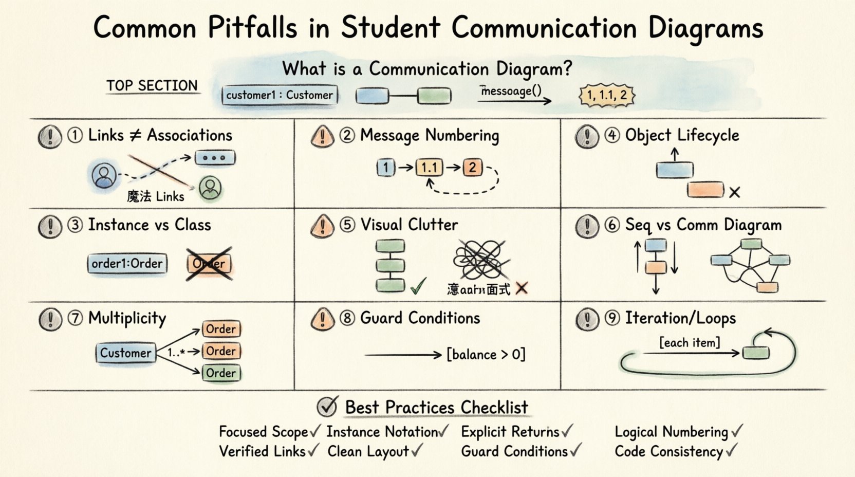
🧠 Understanding the Foundation: What is a Communication Diagram?
Before addressing errors, it is vital to establish what a Communication Diagram actually represents. In the context of Unified Modeling Language (UML), this diagram is a type of interaction diagram. It focuses on the structural organization of objects and the messages they exchange. Unlike a Sequence Diagram, which emphasizes time and order on a vertical axis, a Communication Diagram emphasizes the spatial arrangement and the links between objects.
When you are learning to design these diagrams, keep these core principles in mind:
- Objects are Instances: The diagram depicts specific instances of classes, not the classes themselves.
- Links are Associations: The lines connecting objects represent established associations or links between them.
- Messages are Actions: The arrows indicate the flow of control and data between objects.
- Sequence is Explicit: Unlike Sequence Diagrams, ordering is shown via message numbers, not vertical position alone.
Students often skip the foundational step of clearly defining the scope of the interaction. A Communication Diagram should focus on a single use case or a specific method call chain. Trying to capture the entire system’s behavior in one diagram often leads to clutter and confusion. Always isolate the interaction you are documenting.
🚧 Pitfall 1: Confusing Links with Associations
One of the most persistent errors involves the distinction between a structural association and a communication link. In UML, an association is a static relationship defined in the class diagram. It represents that one class knows about another. A link is a specific runtime instance of that association.
When students draw Communication Diagrams, they frequently draw lines between objects that do not actually have a direct relationship. This creates a “magic link” scenario where Object A can send a message to Object B, even though no path exists in the system architecture.
Why This Happens
This error usually stems from a lack of a defined class model. If the class diagram is not solid, the communication diagram becomes a guessing game. Students might assume two objects need to talk because they both participate in a feature, without verifying if they are connected directly.
How to Avoid It
- Verify Class Diagrams: Always cross-reference your class diagram. Ensure a link exists before drawing a line in the communication diagram.
- Use Roles: Label the ends of the links with role names. This clarifies the direction and nature of the relationship.
- Check Navigation: Ensure that the object sending the message actually holds a reference to the receiving object.
🔢 Pitfall 2: Message Numbering and Sequence Logic
Communication Diagrams rely on numbered messages to indicate the order of execution. A common mistake is the misuse of these numbers, leading to logical impossibilities in the system flow.
The Circular Dependency Error
Students sometimes number messages in a way that suggests a circular dependency without proper recursion handling. For example, if Object A calls Object B, and Object B calls Object A, the numbers must reflect a clear return path. If the numbers do not align with the return messages, the diagram implies a deadlock or an infinite loop.
The Missing Return Value
Another frequent issue is omitting the return message entirely. In many diagrams, students draw the call arrow but forget to draw the return arrow. While this is sometimes acceptable in high-level sketches, it makes the diagram incomplete for detailed design.
Best Practices for Sequencing
- Sequential Numbering: Use integers (1, 2, 3) for the main sequence. Use decimal points (1.1, 1.2) for nested calls within a step.
- Explicit Returns: Draw a dashed line with an arrowhead for the return message. Label it if it carries significant data.
- Parallel Calls: If messages happen simultaneously, use the same number or indicate parallelism clearly. Do not force a linear order if the design allows concurrency.
🏷️ Pitfall 3: Object Instance vs. Class Representation
Clarity in naming is essential. A Communication Diagram must show instances. The standard notation for an instance is objectName : ClassName. Students often default to drawing classes, which leads to ambiguity about whether the behavior applies to a single object or the entire type.
The Generic Label Mistake
Using a generic label like Customer instead of customer1 : Customer is a significant error. It blurs the line between the blueprint (class) and the building (instance). This confusion can lead to implementation errors where developers instantiate objects incorrectly.
Multiple Instances of the Same Class
When a class participates in an interaction multiple times, it must be represented as multiple distinct instances. For example, if a Order object interacts with two different Payment objects, you cannot draw just one Payment box with multiple lines coming from it unless you specify that they are the same instance. If they are different instances, they need different names.
Correct Notation Checklist
- Prefix Name: Always include a unique name prefix (e.g., order1).
- Colon Separator: Use a colon to separate the instance name from the class name.
- Consistency: Ensure the class name matches the actual code structure.
🔄 Pitfall 4: Ignoring Object Lifecycle and State
A Communication Diagram describes a snapshot of behavior, but it often ignores the lifecycle of the objects involved. Students might depict an object sending a message when that object should logically not exist yet, or when it has already been destroyed.
Destruction Markers
If an object is created and then destroyed within the interaction sequence, this should be indicated. While not always mandatory for high-level diagrams, omitting this can mislead a developer about memory management responsibilities. The “X” mark on an object instance indicates destruction.
State Dependency
Some messages are only valid if an object is in a specific state. For example, a checkout message on a Cart object is invalid if the Cart is already in the Completed state. While Communication Diagrams do not explicitly show state charts, the flow should not imply impossible transitions.
📐 Pitfall 5: Layout and Visual Clutter
UML diagrams are meant to be read. If the visual arrangement is chaotic, the technical content becomes useless. Students often place objects randomly without considering the flow of information.
The “Spaghetti” Layout
Crossing lines make it difficult to trace the path of a message. When lines intersect, it becomes hard to tell which message belongs to which link. This is a design failure, not just a cosmetic one.
Spacing and Alignment
Consistent spacing helps the eye follow the sequence. Group related objects together. If Object A, B, and C interact frequently, place them closer than Object D, which is only peripherally involved.
Table: Layout Do’s and Don’ts
| Aspect | Do ✅ | Don’t ❌ |
|---|---|---|
| Object Positioning | Group interacting objects logically | Scatter objects randomly across the canvas |
| Line Crossing | Avoid crossing lines where possible | Allow excessive line intersections |
| Message Labels | Place text near the arrow shaft | Overcrowd the diagram with text blocks |
| Direction | Left-to-Right or Top-to-Bottom flow | Bi-directional arrows without clear logic |
🆚 Pitfall 6: Confusing Sequence and Communication Diagrams
Students often mix the intent of Sequence Diagrams and Communication Diagrams. While they are both interaction diagrams, their strengths differ. Using a Communication Diagram when a Sequence Diagram is required (or vice versa) leads to communication gaps within the development team.
When to Use Which
- Sequence Diagram: Best for showing detailed timing, activation bars, and strict temporal ordering. Use when time is critical.
- Communication Diagram: Best for showing the topology of objects and the overall structure of the interaction. Use when the relationships matter more than the exact millisecond timing.
The Hybrid Mistake
A common error is trying to cram Sequence Diagram features (like activation bars and time axes) into a Communication Diagram. This violates the standard and confuses the reader. Stick to the specific conventions for the diagram type you are drawing.
🛠️ Pitfall 7: Neglecting Multiplicity and Navigation
Multiplicity defines how many instances of a class can be associated with another. In a Communication Diagram, this is often overlooked. Students draw a link between two objects without considering if the link supports one-to-one, one-to-many, or many-to-many relationships.
The Single Link Assumption
If a Customer has many Orders, a Communication Diagram showing a single Customer linking to a single Order is technically correct for that specific interaction. However, failing to acknowledge the potential for multiple orders can lead to logic errors in the code that handles the collection.
Navigation Direction
Links in UML have a direction. You cannot send a message up a link if the association is unidirectional in the class model. Students often assume bidirectional communication is possible simply because they want the objects to talk.
📝 Pitfall 8: Omitting Guard Conditions
Guard conditions are boolean expressions that determine if a message is sent. For example, [balance > 0] before allowing a withdrawal. Students frequently omit these guards in Communication Diagrams, making the diagram appear as if the action always occurs.
Why It Matters
Without guards, the diagram suggests unconditional behavior. This can lead to bugs where the system attempts an action that is invalid under certain conditions. Guard conditions add necessary context to the message flow.
How to Include Them
- Bracket Notation: Place the condition in square brackets near the message arrow.
- Clarity: Keep conditions concise. If the logic is complex, document it separately.
- Consistency: Ensure the guard matches the logic in the class methods.
🧩 Pitfall 9: Overlooking Iteration and Loops
Real-world systems often involve loops. A student might list five messages for five items in a list. This makes the diagram repetitive and hard to read. Instead, the diagram should indicate an iteration.
The Unrolled Loop
Writing out every iteration is a waste of space and clarity. It hides the pattern. If an object iterates over a collection, this should be noted explicitly.
Using the Alt/Loop Frame
While Communication Diagrams do not have the same frame syntax as Sequence Diagrams, the concept of iteration should be clear. You can label a message as [each item] to indicate that the action repeats. Do not draw the same arrow five times.
✅ Best Practices Checklist for Students
To ensure your Communication Diagrams are robust and professional, review this checklist before finalizing your work.
- Scope: Is the diagram focused on a single use case?
- Instances: Are all objects labeled as instances (name : Class)?
- Links: Do all links exist in the class diagram?
- Numbering: Are message numbers logical and sequential?
- Returns: Are return messages shown where necessary?
- Clarity: Is the layout clean with minimal crossing lines?
- Context: Are guards and conditions included for complex logic?
- Consistency: Do the names match the codebase?
🔍 Deep Dive: The Impact of Errors on Development
Why does it matter if a student draws a Communication Diagram incorrectly? The impact extends beyond the classroom.
Documentation Drift
Code documentation often relies on these diagrams. If the diagram is wrong, the documentation becomes a lie. Developers reading the diagram will assume a link exists where it does not, leading to compilation errors or runtime exceptions.
Onboarding Difficulty
New team members rely on diagrams to understand the system architecture. A confusing diagram increases the time required to onboard new engineers. It creates friction and slows down the development velocity.
Refactoring Risks
When refactoring code, the diagram serves as a map. If the map is wrong, the team might refactor the wrong components. They might remove a class that was actually critical, or leave dead code that was supposed to be removed.
🧪 Practical Example: Correcting a Flawed Diagram
Consider a scenario where a Student enrolls in a Course. A flawed diagram might show the Student object directly calling a method on the Course object without an intermediary.
The Flaw
The Student and Course classes might not have a direct association. The enrollment process often involves a Registrar or EnrollmentService. Direct communication bypasses the business logic handled by the service layer.
The Correction
The corrected diagram should introduce the Registrar object. The Student sends a request to the Registrar, which then communicates with the Course. This adds layers of abstraction and adheres to the Single Responsibility Principle. It also clarifies the link structure.
Key Takeaway
Always model the system as it is designed, not just as it is convenient for the diagram. If an object needs to know another, there must be a structural reason for that knowledge.
🎓 Final Thoughts on Diagram Integrity
Mastering the creation of Communication Diagrams is a journey of precision and attention to detail. It requires a deep understanding of object-oriented principles and the specific syntax of UML. By avoiding the common pitfalls outlined above, you create diagrams that serve their true purpose: communication.
These diagrams are not just drawings; they are contracts between the design and the implementation. When you ensure that every link, message, and instance is accurate, you build a foundation for reliable software. Take the time to review your work, check against the class model, and verify the logical flow. With practice, these diagrams will become a natural part of your design process, enhancing clarity and reducing errors in the final product.
Remember, the goal is not to create a perfect picture, but a useful one. Focus on the interactions that matter. Ignore the noise. Prioritize the connections that drive the system forward. This approach will yield diagrams that are both technically accurate and easy to understand.