
UML State Machine Diagrams, often referred to as State Diagrams, are critical tools for modeling the dynamic behavior of systems. They define how an object responds to events over time. However, creating an accurate model requires precision. Many engineers and analysts fall into traps that compromise the clarity and utility of the diagram. This guide examines ten frequent errors and provides actionable solutions to ensure your state modeling is robust and maintainable.
When a state diagram fails to represent the logic correctly, the downstream impact is significant. It leads to ambiguous requirements, implementation bugs, and difficulty in debugging. By understanding these common pitfalls, you can create diagrams that serve as reliable documentation for development teams.
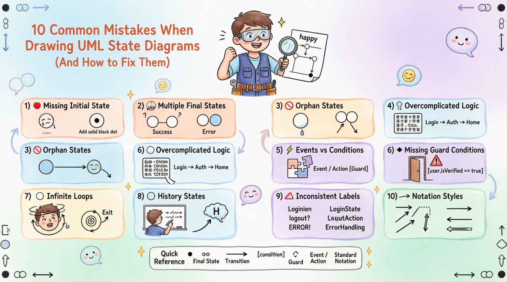
1. Missing the Initial State 🔴
The most fundamental error is failing to define where the system begins. Every valid state machine must have exactly one initial state, represented by a solid filled circle. Without this anchor point, the lifecycle of the object is undefined.
- Why it matters: Developers need to know the default entry point for the system. If the initial state is missing, the object might initialize in an undefined state.
- The Fix: Always start your diagram with the initial pseudo-state. Ensure that the first transition flows logically from this point.
- Visual Check: Look for the black dot. If it is absent, the diagram is technically invalid according to UML standards.
2. Multiple Final States Without Context 🏁
While it is permissible to have multiple final states (represented by a double-concentric circle), doing so without clear distinction creates confusion. A diagram might end in a success state or a failure state, but if they look identical, the outcome is unclear.
- Why it matters: Stakeholders need to understand the termination condition. Is the process complete, or did it crash?
- The Fix: Use distinct labels for each final state. For example, label one as “Completed Successfully” and another as “Terminated by Error”.
- Visual Check: Ensure the text labels near the final states are descriptive and unambiguous.
3. Orphan States (No Transitions) 🚫
An orphan state is a state that has no incoming or outgoing transitions. It exists in the diagram but is unreachable or cannot lead anywhere. This breaks the flow of logic.
- Why it matters: An unreachable state suggests dead code or a logic gap. An unreachable exit implies the system gets stuck.
- The Fix: Review every state node. Ensure every state has at least one incoming arrow and one outgoing arrow, unless it is the initial or final state.
- Visual Check: Scan the diagram for isolated circles. If a state floats without lines connecting to it, it is an error.
4. Overcomplicating State Logic 🧩
State diagrams are meant to show *behavior*, not *implementation details*. A common mistake is embedding complex algorithms or extensive logic descriptions directly inside a state box.
- Why it matters: If a state box contains too much text, the diagram becomes cluttered and hard to read. It defeats the purpose of visual modeling.
- The Fix: Keep state labels concise. Move complex logic to the transition guard conditions or external documentation. Use sub-states (composite states) to break down complexity if necessary.
- Visual Check: If a state box requires scrolling to read, it is too large. Break it down.
5. Confusing Events with Conditions ⚡
Events trigger transitions, while conditions (guards) determine if the transition can happen. Mixing these up leads to incorrect logic flow.
- Why it matters: An event like “Button Press” should trigger a move. A condition like “[IsAuthorized]” should filter the move. Swapping them changes the system behavior.
- The Fix: Use the standard notation: EventName/Action [Guard]. If there is no guard, omit the brackets. If there is no action, omit the slash.
- Visual Check: Verify that brackets are used exclusively for boolean logic and slashes separate the trigger from the action.
6. Ignoring Guard Conditions 🛑
Transitions often depend on specific criteria being met. Omitting guard conditions implies that a transition is always possible, which is rarely true in complex systems.
- Why it matters: Without guards, the system might attempt to move to a state it cannot enter. This causes runtime errors.
- The Fix: Add square brackets to transitions where logic applies. For example, [User Logged In] or [Inventory Available].
- Visual Check: Look for transitions that seem too easy. Ask if there are any prerequisites that should block that path.
7. Circular Dependencies Without Exit ⭕
Creating a loop where a system can cycle indefinitely without an escape route can cause infinite loops in the software.
- Why it matters: While some loops are intentional (e.g., a retry mechanism), they must have a clear exit condition to prevent hanging processes.
- The Fix: Ensure every loop has a termination path. Label the exit condition clearly, such as [Retry Limit Exceeded].
- Visual Check: Trace the path of the loop. Can you find a way out? If not, add a transition that breaks the cycle.
8. Neglecting History States 📜
When a system re-enters a composite state, it often needs to remember where it left off. Ignoring history states forces the system to restart from the beginning every time.
- Why it matters: This creates a poor user experience and unnecessary processing overhead. It disrupts the continuity of the workflow.
- The Fix: Use a deep history pseudo-state (H with a slash) to indicate returning to the last active sub-state. Use a shallow history (H) for the parent state.
- Visual Check: If a state machine branches and returns, verify if it needs to remember its previous position.
9. Inconsistent Labeling Conventions 🏷️
Using different naming styles for the same concepts makes the diagram confusing. Some states might be verbs, others nouns, or mixed with abbreviations.
- Why it matters: Consistency aids readability and maintenance. Inconsistency leads to misinterpretation by different team members.
- The Fix: Establish a naming convention before drawing. Use nouns for states (e.g., “Processing”) and verbs for transitions (e.g., “Starts Processing”).
- Visual Check: Read through the labels. Do they follow a consistent grammatical structure?
10. Inconsistent Notation Styles 📐
UML has specific rules for arrows, line styles, and shapes. Deviating from these standards can make the diagram look unprofessional and confusing.
- Why it matters: Standard notation ensures that anyone familiar with UML can read the diagram immediately.
- The Fix: Use solid arrows for transitions. Use dashed arrows for signals or events if required by your specific modeling standard. Keep line thickness uniform.
- Visual Check: Ensure all state shapes are circles and all transitions are lines with arrowheads.
Quick Reference: State Diagram Best Practices
| Component | Correct Usage | Common Error |
|---|---|---|
| Initial State | Solid filled circle | Missing entirely |
| Final State | Double concentric circle | Single circle or square |
| Transition | Solid line with arrow | Dotted line without arrow |
| Guard Condition | Text in square brackets [ ] | Text without brackets |
| Event | Text before slash / | Text after slash / |
| State Label | Concise noun or verb | Long paragraph of text |
Impact of Correct Modeling 📈
Adhering to these guidelines does more than just create a pretty picture. It reduces ambiguity during the development phase. When requirements are clear, the code written reflects the intended logic more accurately. This reduces the need for refactoring later.
Furthermore, well-structured state diagrams serve as excellent documentation for onboarding new team members. A junior developer can understand the lifecycle of a critical object without needing constant clarification from seniors. This autonomy improves team velocity.
Consider the maintenance aspect. Software evolves. If the diagram is messy, updating it becomes a chore. If it is clean and follows standard conventions, updates are straightforward. This longevity is a key benefit of avoiding these common mistakes.
Final Thoughts on State Machine Design 🎯
Building a UML State Diagram is an exercise in clarity. It requires discipline to resist the temptation to include every detail in the visual model. By focusing on the essential flows and adhering to standard notation, you create a tool that serves the project effectively.
Review your diagrams regularly. Ask peers to critique them. Often, a fresh pair of eyes can spot an orphan state or a confusing transition that the original author missed. Continuous improvement of your modeling skills ensures that your documentation remains a valuable asset throughout the software lifecycle.