
State Machine Diagrams, often referred to as State Charts, are a critical component of the Unified Modeling Language (UML). They provide a visual representation of the dynamic behavior of a system or object. Unlike static structure diagrams, state diagrams focus on how an entity responds to changes in its environment over time. At the heart of this modeling technique lie two fundamental concepts: Transitions and Events. Understanding the mechanics of these elements is essential for designing robust, predictable software architectures.
When modeling complex systems, simply knowing when a state exists is not enough. You must define precisely how the system moves from one condition to another. This movement is governed by transitions, which are triggered by events. Without a clear definition of these triggers and the conditions under which they fire, a state model remains incomplete and potentially ambiguous. This guide explores the technical nuances of transitions and events, ensuring that your models communicate intent clearly to developers and stakeholders.
📝 The Anatomy of a Transition
A transition represents a change of state from a source to a target. It is not merely a line connecting two shapes; it is a directional arrow carrying specific logic. In UML, a transition can be drawn as a straight line or a curve, but the syntax associated with it defines its behavior. Every transition typically consists of three distinct parts, though not all are mandatory in every implementation.
- Trigger (Event): The condition that initiates the transition. This could be a signal received, a method call, a timer expiration, or a change in data.
- Guard Condition: A Boolean expression that must evaluate to true for the transition to occur. It acts as a filter on the trigger.
- Effect (Action): The activity performed when the transition is executed. This can involve updating variables, sending signals, or invoking operations.
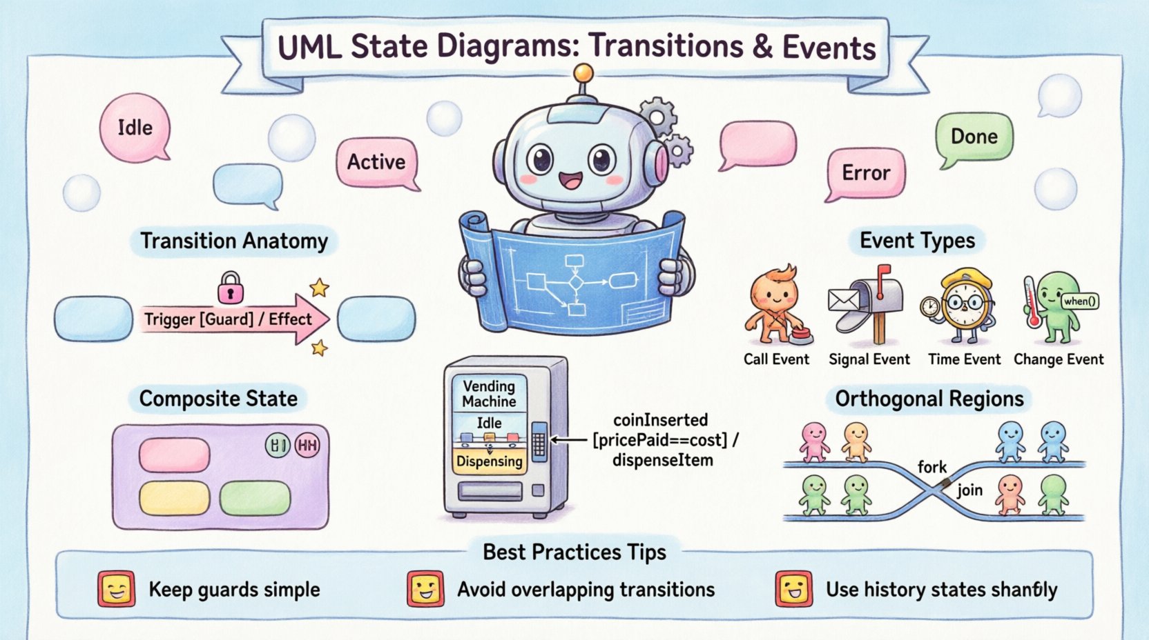
The standard notation for a transition is often written as:
Trigger [Guard] / Effect
If the guard condition is omitted, the transition is assumed to fire whenever the trigger occurs, provided the system is in the source state. If the guard evaluates to false, the transition is ignored, and the system remains in the current state until another valid trigger or guard combination is met. This mechanism prevents unintended state changes based on incomplete data.
⚡ Event Definitions and Classifications
Events are the catalysts for state changes. In UML, events are categorized based on their origin and timing. Understanding these categories helps in designing systems that react appropriately to both internal logic changes and external stimuli.
1. Call Events
A call event occurs when a specific operation is invoked on the object. This is the most common form of event in object-oriented design. For example, a method named startEngine() might trigger a transition from a Stopped state to a Running state.
2. Signal Events
Signal events represent asynchronous messages received from other objects or external systems. Unlike call events, signals are decoupled from the receiver’s current execution thread. This is crucial for modeling systems that must handle concurrent inputs without blocking.
3. Time Events
Time events trigger transitions based on the passage of time. These are often used for timeout mechanisms, periodic checks, or scheduled tasks. A time event might be specified as timeout(5s), indicating a transition after five seconds of inactivity.
4. Change Events
Change events are triggered when a specific condition regarding data becomes true. The syntax typically involves the keyword when followed by a Boolean expression. For instance, when (temperature > 100) could trigger a transition to a Overheat state.
The table below summarizes the primary event types and their typical use cases:
| Event Type | Trigger Mechanism | Typical Use Case |
|---|---|---|
| Call Event | Method Invocation | User Actions, API Requests |
| Signal Event | Asynchronous Message | System Alerts, Inter-module Comm |
| Time Event | Timer Expiration | Timeouts, Periodic Maintenance |
| Change Event | Data Condition Met | Threshold Checks, State Flags |
🔒 Guard Conditions and Logic
A guard condition is a Boolean expression enclosed in square brackets, appearing after the event trigger. It serves as a validation step. Even if the trigger event occurs, the transition will not execute unless the guard evaluates to true. This is vital for enforcing business rules directly within the state model.
For example, consider a vending machine. A transition from Idle to Dispensing might be triggered by a coinInserted event. However, a guard condition might be required: [pricePaid == itemCost]. Without this guard, the machine might dispense the item even if the credit is insufficient, violating the logic of the system.
Key principles for guard conditions include:
- State Independence: Guards should generally depend on the state of the object, not external global variables, to maintain encapsulation.
- Predictability: Complex logic inside guards can make the model hard to read. If logic is extensive, consider moving it into the Action part of the transition.
- Deadlocks: Ensure that for every state, there is at least one valid path out if the system is expected to progress. Otherwise, the system may hang.
🏃 Actions and Effects
Actions are the executable parts of a transition. They describe what happens as a result of the transition taking place. Actions can be simple assignments, method calls, or complex algorithms. They are placed after a forward slash / following the guard condition.
There are different contexts where actions are executed:
- Entry Action: Executed when entering a state. Denoted by
entry / action. - Exit Action: Executed when leaving a state. Denoted by
exit / action. - Do Action: Executed continuously while in a state, provided no other event triggers a transition. Denoted by
do / action. - Transition Action: Executed during the transition itself, immediately after the guard passes.
It is important to distinguish between the transition action and the state entry action. If a transition leads to a state, both the transition action and the entry action of the target state will execute. This allows for a two-step initialization process: first, update the context via the transition, then initialize the new state.
🔄 State Internal Activities
States are not static containers; they possess behavior. The behavior of a state is defined by its internal activities. These activities allow an object to maintain its state while reacting to events without changing its current state classification.
Internal Transitions
An internal transition is a transition that originates from and targets the same state. It is often used to handle events that require a response but do not warrant a change in the high-level state of the object. For example, a Locked state might receive a displayTime signal. The display updates, but the object remains Locked.
The syntax for an internal transition often omits the target state, as it is implied to be the source state. This keeps the diagram cleaner by avoiding self-looping arrows for minor interactions.
Do Activities
The do activity is unique because it represents continuous activity. It is typically associated with a timer or a polling mechanism. If the object is in a Monitoring state, the do activity might be checkSensors(). This continues until a different event, such as alarmTriggered, occurs and initiates a transition to a different state.
🏗️ Composite States and Hierarchy
Real-world systems are rarely flat. They contain nested logic. Composite states allow you to group multiple sub-states within a single state. This hierarchy reduces complexity and organizes behavior logically. A composite state acts as a container for a sub-chart.
When a composite state is entered, a default initial pseudo-state within it is activated. This ensures that the sub-states start in a known configuration. Transitions can exist both inside the composite state and outside it.
Benefits of using composite states include:
- Modularity: Complex logic is encapsulated within a sub-chart.
- Reusability: Common sub-state patterns can be replicated across different parts of the diagram.
- Readability: High-level views can show a single state, while detailed views drill down into the sub-states.
Transitions can also target a composite state. When this happens, the system enters the initial sub-state of that composite state automatically. This ensures a consistent starting point for the nested behavior.
🕰️ History States: Shallow and Deep
History states are special pseudo-states that remember where the system was before leaving a composite state. This is particularly useful for interrupt-driven systems where a process is paused and later resumed.
Shallow History
A shallow history state is denoted by a circle with an H inside. It remembers the last active state within the composite state, but only at the top level. If the system was in a sub-state of a sub-state, the shallow history will only recall the immediate parent state of the composite state.
Deep History
A deep history state is denoted by a circle with a double H inside. It remembers the exact sub-state configuration, including nested levels. When a deep history transition occurs, the system re-enters the specific sub-state where it left off, rather than the initial state of the composite container.
This distinction is critical for maintaining context in long-running processes. For example, in a document editor, a Editing composite state might contain sub-states like Typing or Reviewing. If the user switches to Printing and then returns, a deep history state ensures they return to Reviewing, not the default Typing state.
⚖️ Orthogonal Regions and Parallelism
p>UML state diagrams can model concurrent behavior using orthogonal regions. An orthogonal region divides a composite state into independent sub-states that exist simultaneously. This is analogous to multiple threads running in parallel within a single object.Orthogonal regions are separated by a solid line within the composite state boundary. Each region can have its own set of states and transitions. Events can trigger transitions in one region without affecting the others, allowing for independent progress.
Key characteristics of orthogonal regions include:
- Simultaneity: The object is in one state within each region at the same time.
- Independence: Transitions in one region do not block transitions in another.
- Global Events: Events can be defined to trigger transitions across multiple regions simultaneously.
This structure is essential for modeling systems where multiple aspects of an object need to be tracked independently, such as a Vehicle object that tracks EngineStatus and NavigationStatus concurrently.
🔄 Fork and Join Semantics
Fork and Join transitions are used to manage the flow of control within orthogonal regions. They allow a single transition to spawn multiple concurrent activities or wait for multiple activities to complete.
Fork
A fork transition splits a single path into multiple parallel paths. It is represented by a solid black bar with multiple outgoing arrows. When the fork is executed, the system transitions into the target states of all outgoing branches simultaneously. This initiates concurrent behavior.
Join
A join transition merges multiple parallel paths into a single path. It is represented by a solid black bar with multiple incoming arrows and a single outgoing arrow. The join waits for all incoming transitions to arrive before proceeding to the next state. This ensures synchronization before continuing.
Using Fork and Join correctly prevents race conditions in the model. It explicitly defines where parallelism begins and ends, ensuring that the system waits for necessary operations to complete before moving forward.
⚠️ Common Pitfalls and Best Practices
Creating accurate state diagrams requires attention to detail. Several common errors can lead to ambiguity or unimplementable logic.
- Missing Initial State: Every state machine must have exactly one initial state. Without it, the system has no defined starting point.
- Missing Final States: While not always mandatory, end states indicate successful termination or error termination. Omitting them makes it unclear how a process concludes.
- Unreachable States: Ensure that every state is reachable from the initial state. Dead states confuse users and indicate logic gaps.
- Overlapping Guards: If multiple transitions leave the same state with the same trigger, guards must be mutually exclusive. If both are true, the behavior is undefined.
- Complex Actions: Keep actions simple. If an action requires extensive logic, move that logic to a separate class or method and call it from the action.
🏁 Final Considerations
Modeling transitions and events is a discipline that bridges the gap between abstract requirements and concrete implementation. By rigorously defining triggers, guards, and effects, you create a blueprint that developers can translate into code with high fidelity.
Remember that state diagrams are living documents. As requirements evolve, the state model must be updated to reflect new behaviors. Regular reviews of the state machine can uncover logical inconsistencies before they become code defects. Focus on clarity and precision. A well-documented state diagram reduces the cognitive load on the development team and ensures that the system behaves as intended under all conditions.
By adhering to UML standards and utilizing the features of transitions and events effectively, you can build systems that are resilient, maintainable, and easy to understand. The effort invested in precise modeling pays dividends during the implementation and maintenance phases of the software lifecycle.