
State Machine Diagrams serve as the backbone for defining the dynamic behavior of systems. They map out how an object responds to events over time. However, as systems scale, the diagrams often become intricate webs of transitions, states, and conditions. When logic flows become convoluted, debugging the underlying behavior turns into a significant challenge. This guide provides a structured approach to identifying and resolving logic errors within complex UML state representations.
Understanding the lifecycle of a state is crucial. A state represents a condition during which an object performs an activity or waits for an event. When multiple states interact, the paths between them define the system’s operational logic. If a transition is missing or a guard condition is flawed, the system may enter an undefined state. This document outlines the methods to validate these flows effectively.
1. Understanding the Anatomy of a Complex State Machine 🧩
Before troubleshooting, one must recognize the components that constitute a state diagram. Complexity often arises not from the number of states, but from the relationships between them. The following elements form the core structure:
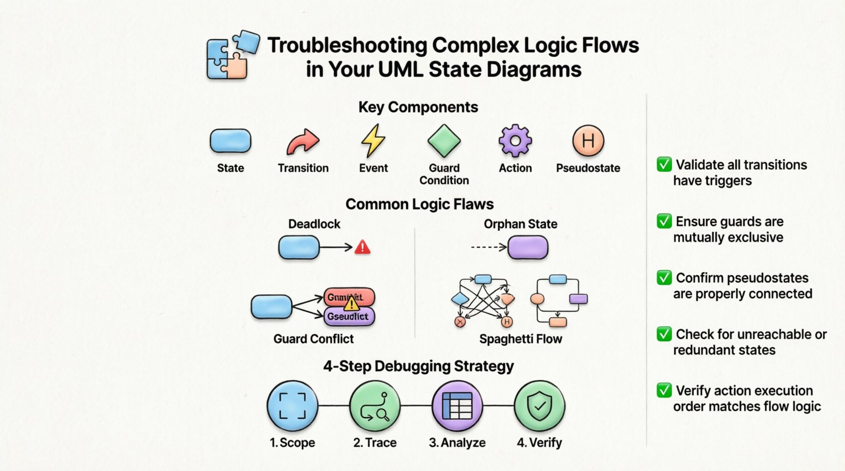
- States: The distinct conditions or modes of operation (e.g., Idle, Processing, Error).
- Transitions: The directed arrows that connect states, indicating a change in condition.
- Events: The triggers that initiate a transition (e.g., User Login, Timeout).
- Guard Conditions: Boolean expressions that must be true for a transition to occur.
- Actions: Operations executed upon entry, during a state, or upon exit.
- Pseudostates: Nodes like Initial, Final, Fork, Join, and History that control flow logic.
When logic flows are complex, these elements interact in non-linear ways. A single event might trigger multiple transitions depending on the current context. This context sensitivity is where errors typically hide. Visualizing the flow requires tracing paths from the initial node to various final or terminal states.
2. Common Logic Flaws and Patterns 🔍
Identifying the specific type of error is the first step in resolution. Below are the most frequent issues encountered during the modeling phase.
2.1 Deadlocks and Orphan States
A deadlock occurs when the system reaches a state where no outgoing transitions are possible, yet the state is not a final state. This halts execution. Conversely, an orphan state is a state that cannot be reached from the initial state. Both indicate a break in the logical continuity.
- Deadlock Signs: A state with no outgoing arrows and no final marker.
- Orphan Signs: A state with no incoming arrows from any reachable path.
- Resolution: Ensure every non-final state has at least one valid outgoing path. Verify that every state is reachable from the start node via a valid event sequence.
2.2 Ambiguous Guard Conditions
Guard conditions determine which path is taken when multiple transitions exist from the same state. If the logic is unclear, the system behavior becomes non-deterministic.
- Conflict: Two transitions from the same state have guard conditions that can both be true simultaneously.
- Gap: All possible conditions are false, leaving no valid transition.
- Optimization: Use mutually exclusive conditions. Ensure the sum of all guard conditions equals the total possibility space (True/False).
2.3 Spaghetti State Flows
When transitions cross over each other excessively without clear grouping, the diagram becomes unreadable. This often leads to missed logic during review.
- Visual Clutter: Lines crossing every other line.
- Logic Gaps: Hard to trace the path of a specific event.
- Fix: Utilize nested states or orthogonal regions to group related logic.
| Flaw Type | Impact | Diagnostic Indicator |
|---|---|---|
| Deadlock | System Freeze | State with no outgoing edges |
| Orphan State | Unreachable Logic | State with no incoming edges |
| Guard Conflict | Non-Determinism | Overlapping boolean conditions |
| Missing Transition | Unhandled Events | Event listed in trigger but no path |
3. Step-by-Step Debugging Strategy 📝
Resolving logic issues requires a systematic trace of the state machine. Follow this workflow to validate the integrity of your diagrams.
3.1 Define the Scope and Boundaries
Before analyzing specific transitions, define the boundaries of the state machine. What are the inputs? What are the expected outputs? Ensure the diagram covers the entire lifecycle of the object being modeled. If a specific state is part of a larger system, verify that the interface events are consistent.
- List all external events that can trigger the machine.
- Define the initial state explicitly.
- Define the termination criteria (final states).
3.2 Trace Event Paths
Simulate the execution manually. Pick a starting state and apply a specific event. Follow the arrow. Note the resulting state. Repeat this process for every possible event from every reachable state.
- Start at Initial: Verify the first transition occurs as expected.
- Follow the Path: Does the guard condition allow passage?
- Check Actions: Are entry and exit actions defined correctly?
- Validate Final State: Does the path end in a logical conclusion?
3.3 Analyze Guard Conditions Mathematically
Treat guard conditions like code. If a state has three outgoing transitions, the logic for each guard must be distinct. Use a truth table to verify coverage.
- Condition A: Is this true?
- Condition B: Is this true?
- Condition C: Is this true?
- Ensure that for any given input, only one condition is true, or the priority is explicitly defined.
3.4 Verify History States
History states (Deep History vs. Shallow History) are often misused. A Deep History state remembers the last active substate, while a Shallow History state only remembers the last active state in the immediate region.
- Check Usage: Ensure you are not using a history state where a simple transition would suffice.
- Check Scope: Verify the history state is within the correct composite state.
- Check Initialization: Ensure the initial substate is defined correctly after a history transition.
4. Advanced Scenarios: Nested and Concurrent States 🧠
Complexity often escalates when introducing hierarchy and concurrency. These features allow for more compact diagrams but introduce significant logic overhead.
4.1 Nested States and Hierarchy
When a state contains other states (substates), transitions can occur within the substate or between the parent and external states. Logic errors here often involve context loss.
- Context Switching: If a transition exits a parent state, does the substate terminate correctly?
- Inherited Transitions: Does the parent state inherit transitions from a higher level?
- Event Propagation: Does an event bubble up to the parent if the substate does not handle it?
To troubleshoot nested states:
- Isolate the parent state and examine its internal logic first.
- Verify that the entry action of the parent state initializes the substates correctly.
- Check if the exit action of the parent state cleans up the substates.
- Ensure that transitions leaving the parent state do not bypass necessary cleanup logic.
4.2 Orthogonal Regions and Concurrency
Concurrent states allow an object to be in multiple states simultaneously. This is represented by orthogonal regions. Logic flow here is difficult to trace because events may affect only one region.
- Region Independence: Ensure transitions in one region do not inadvertently block transitions in another.
- Synchronization: Use Fork and Join nodes to manage the start and end of concurrent activities.
- Event Filtering: Verify that events are routed to the correct region.
| Feature | Risk Factor | Mitigation Strategy |
|---|---|---|
| Nested States | Context Loss | Trace Entry/Exit Actions |
| History States | Stale State Return | Validate Substate Initializers |
| Fork/Join | Deadlock in Concurrency | Verify All Paths Converge |
| Orthogonal Regions | Event Routing Errors | Map Events to Specific Regions |
5. Validation and Verification Techniques 🔒
Once the diagram is constructed, it must be validated against the requirements. This process ensures the model reflects the intended system behavior.
5.1 Static Analysis
Review the diagram without executing it. Look for structural integrity.
- Completeness: Are all states connected?
- Reachability: Can every state be reached?
- Consistency: Are naming conventions consistent across states and events?
- Redundancy: Are there duplicate states that perform the exact same function?
5.2 Dynamic Simulation
If the modeling tool supports it, run a simulation. Feed test events and observe the state changes. Compare the actual output against the expected output.
- Test Case 1: Normal operation flow.
- Test Case 2: Error handling flow.
- Test Case 3: Edge case handling (e.g., rapid event firing).
- Test Case 4: Timeout scenarios.
5.3 Peer Review
Have another expert review the diagram. Fresh eyes often spot logical gaps that the creator missed. Focus the review on the complex logic flows identified in earlier sections.
- Walkthrough: Have the reviewer trace a specific scenario.
- Challenge: Ask “What happens if X event occurs in State Y?”
- Documentation: Ensure comments explain the rationale behind complex decisions.
6. Maintenance and Evolution of State Models 🔄
Systems evolve. Requirements change. A state diagram that was correct today may be flawed tomorrow. Maintenance is an ongoing process.
- Version Control: Keep track of changes to the diagram. Note which logic changes affected which transitions.
- Impact Analysis: When adding a new state, check all existing transitions that might interact with it.
- Refactoring: If the diagram becomes too large, consider splitting it into sub-diagrams or using composite states more aggressively.
- Documentation Updates: Update the accompanying text documentation whenever the diagram changes to ensure alignment.
7. Checklist for Logic Flow Review ✅
Use this checklist before finalizing any complex state diagram. It covers the critical areas identified throughout this guide.
- ☐ Is the Initial State clearly marked?
- ☐ Are all Final States marked as such?
- ☐ Does every non-final state have at least one outgoing transition?
- ☐ Are all states reachable from the Initial State?
- ☐ Do guard conditions cover all possible outcomes (no gaps)?
- ☐ Are guard conditions mutually exclusive where necessary?
- ☐ Are nested state transitions properly scoped?
- ☐ Do History states reference the correct substates?
- ☐ Are Fork and Join nodes balanced?
- ☐ Are entry and exit actions defined for complex states?
- ☐ Are event names consistent across the diagram?
- ☐ Have edge cases been tested for logic coverage?
Final Considerations for Model Integrity 🎯
Ensuring the logic flows correctly in your UML state diagrams is a critical task for system architects and developers. By systematically analyzing transitions, validating guard conditions, and reviewing hierarchical structures, you can prevent runtime errors and ensure robust behavior. The complexity of modern systems demands rigorous modeling practices. Regular reviews and adherence to the debugging strategies outlined here will maintain the integrity of your designs over time. Focus on clarity, consistency, and thoroughness to create state machines that accurately reflect the system’s reality.


")