
Modeling system behavior requires precision. When you construct a UML State Machine Diagram, the expectation is a clear map of how a system responds to events over time. However, many practitioners encounter diagrams that fail to translate into working logic or create ambiguity during implementation. These failures often stem from subtle structural flaws, misunderstood transition rules, or oversimplified representations of complex concurrency.
This guide provides a diagnostic framework to identify and resolve issues within your State Machine Diagrams. We will examine syntax, logic, hierarchy, and concurrency without relying on specific tools. The goal is to ensure your models are robust, verifiable, and ready for execution.
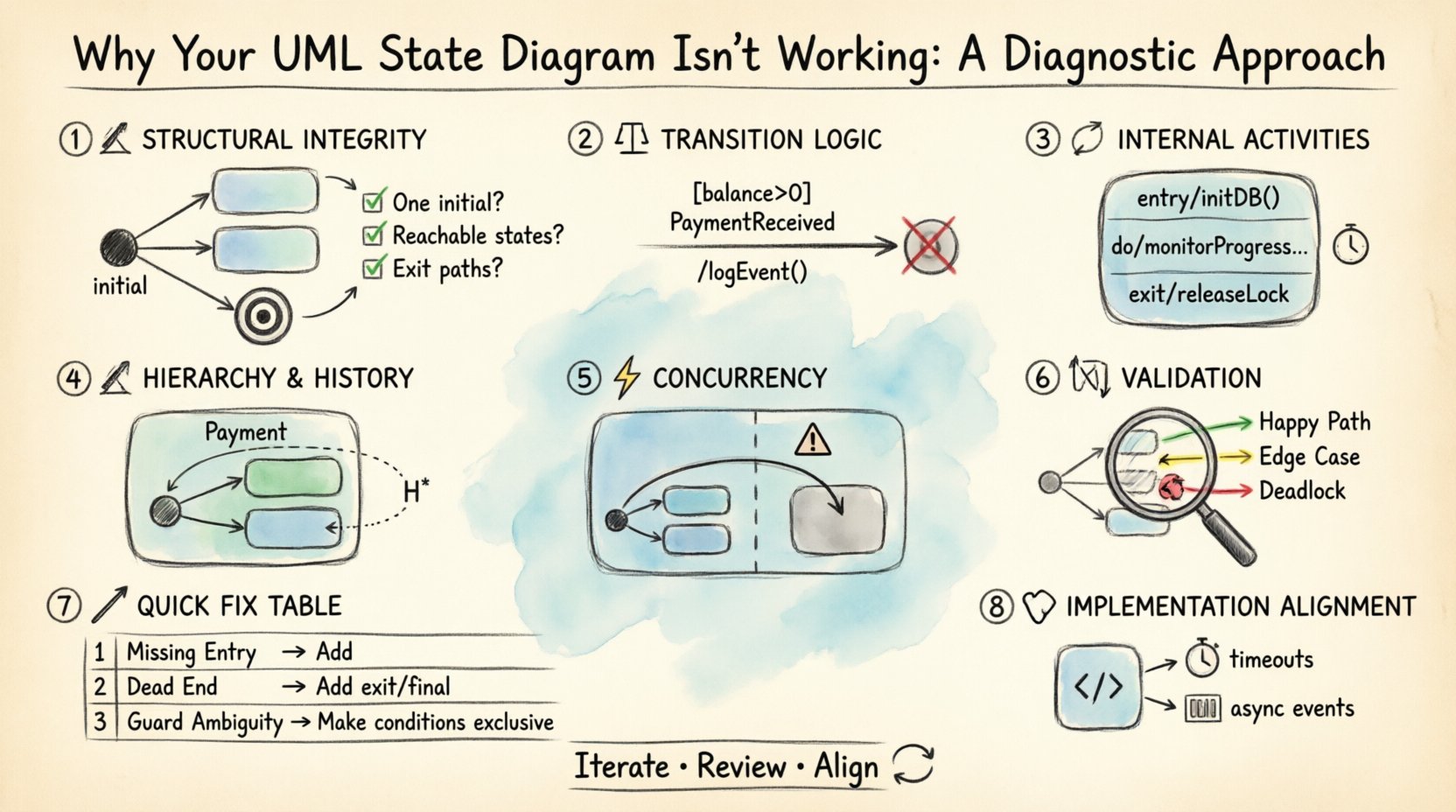
1. Structural Integrity: The Foundation of State Machines 🏗️
Before diving into complex logic, you must verify the basic structural components. A diagram missing fundamental elements will fail to initialize or terminate correctly. This section covers the essential nodes that every valid state machine requires.
- Initial State: Every state machine must have a single entry point. This is typically represented by a filled circle. If you have multiple initial states, the model is invalid because the system cannot determine where to start execution.
- Final State: Similarly, a valid diagram should define where the lifecycle ends. While some systems run indefinitely, most business logic processes require a clear termination condition. Without a final state, the diagram may imply an infinite loop where none exists.
- Connectivity: Every state (except the initial) must be reachable. If a state is isolated, it will never be entered. Conversely, if a state has no outgoing transitions and is not a final state, it is a “dead end” that causes the system to hang.
Diagnostic Checklist for Structure
- Is there exactly one initial state? ✅
- Is there at least one final state? ✅
- Can every state be reached from the initial state? ✅
- Do all non-final states have an exit path? ✅
If you find gaps here, no amount of complex logic will fix the diagram. Correct the topology first.
2. Transition Logic and Guard Conditions ⚖️
Transitions are the arrows connecting states. They define the triggers that move the system from one condition to another. This is where most logical errors occur. A transition without a clear trigger is a guess, not a model.
The Transition Event
Every transition arrow requires an event label. This event represents the signal, message, or internal condition that activates the move. If you omit the event, the transition is a default path that might trigger at any time, leading to race conditions in the actual system.
- Event Naming: Events should be descriptive. Avoid generic terms like “Action” or “Process.” Use specific triggers like
PaymentReceivedorTimeoutExpired. - Event Scope: Ensure the event is defined within the context of the system. Does the state machine listen for this event globally, or is it local to a specific region?
Guard Conditions
Events alone are often insufficient. You may need to check if a specific condition is met before allowing the transition. This is the role of the guard condition. It is a boolean expression placed inside square brackets, such as [balance > 0].
Common pitfalls include:
- Missing Guards: If a transition can happen in multiple states, but only one is valid, you must use guards to distinguish them. Without guards, the model allows invalid paths.
- Complex Logic: Avoid embedding database queries or external API calls inside guard conditions. Guards should evaluate instantly based on local variables. If the check takes time, the state machine may block.
- Contradictions: Ensure guards do not conflict. If State A requires [x=1] and State B requires [x=2], verify that the transition logic handles the switch correctly without ambiguity.
Action Effects
Transitions can also perform actions, denoted by a slash and text (e.g., /logEvent()). Ensure these actions are defined clearly. If an action modifies a variable, ensure the receiving state expects that variable to be changed.
3. Internal Activities: Entry, Exit, and Do 🔄
States are not just waiting rooms; they perform work. Understanding the internal lifecycle of a state is crucial for accurate behavior modeling. Confusion here often leads to timing issues in the implementation.
Entry and Exit Activities
When a state is entered, an Entry Activity runs. When it is exited, an Exit Activity runs. These are distinct from the actions on the transition itself.
- Entry: Use this to initialize variables, start timers, or acquire resources required for the state. For example, when entering a
Processingstate, you might start a database connection. - Exit: Use this to clean up. Stop timers, release locks, or save state data. If you forget to exit properly, you may leave the system in a corrupted state.
The Do Activity
The Do Activity is the work performed while the state remains active. It runs continuously until a transition occurs. This is often confused with Entry Activities.
- Entry vs. Do: Entry runs once upon entering. Do runs repeatedly or continuously while in the state.
- Event Interruption: If an event triggers a transition, the Do activity usually stops. Ensure your diagram reflects this interruption behavior. If the Do activity must continue despite events, the model needs a different structure.
4. Hierarchical States and History 🏗️
Flat state diagrams become unmanageable quickly. Hierarchical states allow you to nest sub-states within a composite state. This reduces visual clutter but introduces complexity regarding how the system enters and exits these nested regions.
Composite States
A composite state contains a cluster of sub-states. The system is in the composite state only when it is in one of the sub-states. This is useful for grouping related behaviors, such as different modes within a Payment state.
Key considerations:
- Entry/Exit Propagation: When the composite state is entered, which sub-state is active? You must define a default entry point for the composite state.
- Transition Scope: Transitions can occur inside the composite state or outside. If an external transition targets the composite state, it enters the default sub-state. If it targets a specific sub-state, it skips the default.
History States
History states allow a composite state to remember its previous configuration. There are two types:
- Shallow History: Remembers the last active sub-state at the top level of the composite state.
- Deep History: Remembers the entire nested configuration, including sub-states within sub-states.
Using history states prevents the need to re-initialize data every time a state is revisited. However, if you misuse them, the system may return to an outdated context, causing data inconsistency.
5. Concurrency and Orthogonal Regions ⚡
Real-world systems often perform multiple tasks simultaneously. A single state machine cannot represent this well without orthogonal regions. This is one of the most difficult concepts to model correctly.
Orthogonal Regions
Orthogonal regions divide a composite state into independent parts. The system exists in a state that is the Cartesian product of the states in each region. Visually, this is often shown with a dashed line dividing the state box.
- Independence: Transitions in Region A do not affect Region B directly. They run in parallel.
- Shared Events: An event can trigger a transition in Region A while Region B is idle. Conversely, an event can trigger changes in both regions simultaneously.
Common Concurrency Errors
- Resource Conflicts: If Region A and Region B both try to write to the same variable, you have a race condition. The diagram should not show this; the implementation must handle synchronization.
- Termination: A composite state with orthogonal regions is only exited when all regions reach a final state or are explicitly terminated. If one region loops forever, the composite state never exits.
- Visual Clarity: If you have more than two regions, the diagram becomes hard to read. Consider splitting the model into separate state machines linked by events if concurrency exceeds two dimensions.
6. Validation and Walkthroughs 🧪
Once the diagram is drawn, it must be validated. This involves tracing paths to ensure logical consistency. Do not skip this step.
Path Analysis
Perform a walk-through of critical scenarios. Start at the initial state and follow every possible path to a final state.
- Happy Path: The most common flow. Does it work?
- Edge Cases: What happens if a user cancels mid-process? What if the network fails? Trace these paths to ensure they lead to a valid state (like an error state) rather than a dead end.
- Deadlocks: Identify loops where no exit is possible. If the system enters a state where no event can trigger a transition, it is deadlocked.
Consistency with Data
Ensure the states align with the data model. If a state is named Verified, does the data object actually have a isVerified flag? If the diagram describes a state that the database cannot represent, the model is abstracted too far from reality.
Common Errors and Fixes Table 📊
Use this table to quickly identify and resolve frequent issues found during diagnostics.
| Issue Category | Common Symptom | Diagnostic Fix |
|---|---|---|
| Missing Entry Point | System does not start | Ensure exactly one filled circle exists as the initial node. |
| Unreachable State | Feature never activates | Trace paths from the initial state; add transitions to connect isolated nodes. |
| Dead End | System hangs | Add outgoing transitions or mark the state as a final state. |
| Guard Ambiguity | Unpredictable behavior | Refine guard conditions to be mutually exclusive or prioritize transitions. |
| History Misuse | Stale data on return | Use Deep History only if nested context must be preserved; otherwise use shallow. |
| Concurrency Conflict | Data corruption | Ensure orthogonal regions do not write to shared variables without locking. |
| Event Naming | Confusion during coding | Use descriptive, event-specific names (e.g., OnUserLogin vs OnLogin). |
7. Implementation Alignment 🧩
A state diagram is a contract. It promises behavior to the developer. If the diagram is ambiguous, the code will be too.
- Variable Scope: Define which variables are global to the machine and which are local to states. The diagram should imply this scope through context.
- Asynchronous Events: If your system handles events asynchronously, ensure the state machine can queue them. A state diagram typically assumes immediate processing. If events are queued, the model must account for buffering.
- Timeouts: Use timers explicitly in the diagram. If a state waits for a response, define what happens if the response does not arrive within a specific timeframe. This is often a guard condition or a specific transition.
8. Iterative Refinement 🔄
State diagrams are rarely perfect on the first draft. Treat them as living documents. As you discover new requirements or edge cases during development, update the diagram.
- Version Control: Treat the diagram file like code. Commit changes when logic shifts significantly.
- Peer Review: Have a colleague trace the paths. They may spot a gap you missed because you are too familiar with the intended flow.
- Code Review: When implementing, compare the code against the diagram. If the code deviates, update the diagram to match. Consistency is more important than the diagram being perfect.
Final Considerations for Stability 🛡️
Maintaining a stable state machine requires discipline. It is easy to add one more transition or one more state, but this accumulates technical debt quickly. Keep the state count manageable. If you find yourself creating hundreds of states, consider splitting the logic into multiple state machines interacting via events.
Always prioritize clarity over cleverness. A simple state machine that is understood by the team is better than a complex one that no one can debug. Focus on the lifecycle of the data and the triggers that change it. If you can explain the diagram to a new developer in ten minutes, it is well-structured.
By following this diagnostic approach, you move from guessing why a diagram fails to knowing exactly which component is broken. This systematic reduction of uncertainty leads to robust systems that behave predictably under all conditions.


")