
Modeling complex systems requires a clear understanding of how entities interact with the software they are building. At the heart of this modeling lies the Use Case Diagram, a fundamental tool in requirements engineering. Among the various elements in a diagram, actor relationships define the scope and boundaries of the system effectively. For new analysts, grasping these connections is crucial for creating accurate blueprints that developers and stakeholders can rely on.
This guide explores the mechanics of actor relationships, the nature of associations, and the nuances of inheritance within system modeling. We will move beyond basic definitions to examine how these elements shape the functionality and behavior of a solution.
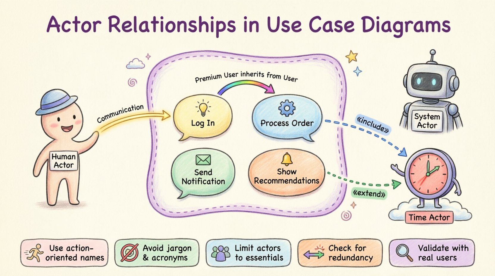
Understanding the Actor Concept 🎭
Before diving into relationships, it is essential to define what an actor represents in a diagram. An actor is a role played by a user or an external system that interacts with the system under discussion. It is not necessarily a specific person, but rather a function or capability required to achieve a goal.
- Human Actors: These represent people who interact with the system directly.
- System Actors: These represent other software systems, hardware devices, or external services that send or receive data.
- Time-Based Actors: Occasionally, a trigger based on time (e.g., a daily batch process) is modeled as an actor.
Analysts must distinguish between a specific user (like “John Smith”) and a role (like “Administrator”). Modeling roles ensures the diagram remains valid even if the personnel changes. This abstraction keeps the focus on what the system does, rather than who is doing it at any given moment.
Defining System Boundaries 🚧
Every Use Case Diagram exists within a defined context. The system boundary is the box that encapsulates the internal logic and processes. Anything outside the box is an actor or an external dependency.
- Inside the Box: Use cases, internal logic, and data processing flows.
- Outside the Box: Actors, external interfaces, and third-party services.
Clarity in boundaries prevents scope creep during development. If a relationship crosses the boundary, it implies a data exchange or a trigger. If it stays inside, it represents internal behavior. Misidentifying the boundary can lead to developers building features that belong in the external system or missing critical integration points.
Types of Actor Relationships 🔗
Relationships describe the nature of interaction between actors and use cases, or between actors themselves. There are four primary relationship types used in this context. Understanding the distinction is key to accurate modeling.
1. Association (Communication) 📡
An association line connects an actor to a use case. It represents a flow of control or data between them. This is the most common relationship.
- Direction: While often bidirectional, the primary flow is usually from the actor initiating the action to the system processing it.
- Labeling: Lines should be labeled if the interaction is ambiguous. For example, “Submit Report” or “Receive Alert”.
- Multiple Actors: A single use case can connect to multiple actors, indicating different roles can trigger the same function.
Example: A “Customer” actor associates with a “Place Order” use case. This indicates the customer initiates the process.
2. Generalization (Inheritance) 🧬
Generalization allows an actor to inherit the capabilities of another actor. This is often used to model specialized roles that share common behaviors with a broader category.
- Parent Actor: The general actor (e.g., “User”).
- Child Actor: The specialized actor (e.g., “Premium User”).
- Behavior: The child actor inherits all associations of the parent. It can also have its own unique associations.
This reduces redundancy. If a “User” can “View Profile,” a “Premium User” can also “View Profile” without drawing a new line. This relationship is typically represented by a solid line with a hollow triangle arrow pointing to the parent actor.
3. Include (Mandatory Dependency) 🔄
An include relationship indicates that a use case must invoke the behavior of another use case to complete its function. It is a mandatory inclusion.
- Usage: Use this when a common step is repeated across multiple use cases.
- Logic: “Log In” might be included in “Update Profile” and “Make Purchase”. Both require authentication.
- Direction: The arrow points from the base use case to the included use case.
Analysts often confuse this with generalization. Remember, generalization applies to actors, while include applies to use cases (though the prompt focuses on actor relationships, the interaction context is vital).
4. Extend (Optional Behavior) ➕
An extend relationship adds optional behavior to a base use case. The extension only happens if specific conditions are met.
- Usage: Use this for error handling, notifications, or optional features.
- Logic: “Search Items” can be extended by “Show Recommendations”. Recommendations only appear if the search returns results.
- Direction: The arrow points from the extending use case to the base use case.
Relationship Types Summary Table 📊
The following table provides a quick reference for distinguishing between the primary relationship types used in modeling.
| Relationship Type | Symbol | Meaning | When to Use |
|---|---|---|---|
| Association | Solid Line | Communication or Data Flow | When an actor triggers a use case. |
| Generalization | Triangle Arrow | Inheritance of Behavior | When one actor is a specialized version of another. |
| Include | Dashed Arrow + «include» | Mandatory Sub-function | When a step is required for the main use case to complete. |
| Extend | Dashed Arrow + «extend» | Optional Behavior | When a feature is conditional or adds to the base flow. |
Best Practices for Modeling Actors 🛠️
Creating a diagram that is both accurate and readable requires discipline. Analysts should follow specific guidelines to ensure the model serves its purpose as a communication tool.
- Keep Names Action-Oriented: Use cases should be named as verbs + nouns (e.g., “Generate Invoice”), while actors are nouns (e.g., “Accountant”).
- Avoid Technical Jargon: Do not name use cases after database tables or API endpoints. Name them after business goals.
- Limit Actor Count: If you have more than 7 actors, consider grouping them or reviewing the scope. Too many actors make the diagram cluttered and hard to read.
- Check for Redundancy: If two actors look similar, determine if they can be merged into a generalization hierarchy.
- Validate with Stakeholders: A diagram is only as good as its acceptance. Review the relationships with business owners to ensure they match real-world processes.
Common Pitfalls to Avoid ⚠️
New analysts often encounter specific challenges when defining relationships. Recognizing these early can save significant rework later in the development lifecycle.
1. Confusing Roles with People
Modeling “John Doe” instead of “Customer” creates fragility. If John leaves the company, the diagram seems broken. Always model the role, not the individual.
2. Over-Complicating Relationships
Every line on a diagram represents a requirement. If a line exists, there is a reason. Avoid drawing lines just to show “connection.” Ensure there is a distinct purpose for every association, such as data entry or data retrieval.
3. Ignoring the System Boundary
Placing a use case inside the boundary that actually belongs to an external system (like a payment gateway) creates confusion. Ensure the boundary reflects the system you are responsible for building, not the entire ecosystem.
4. Mixing Levels of Abstraction
Do not mix high-level business goals with low-level technical steps. “Login” is a technical process. “Access System” is a business goal. Keep the diagram focused on the business value or the specific functional requirement, not both simultaneously.
Refining the Actor Model 🧐
Once the initial draft is complete, the analyst must refine the model. This involves a process of validation and simplification.
- Identify Missing Actors: Are there external systems needed to fulfill the use cases? For example, does “Email Notification” require an “Email Server” actor?
- Verify Generalization: Do the specialized actors really inherit everything from the parent? If a child actor has no new behaviors, it might not need to exist separately.
- Check Data Flow: Ensure that the direction of data flow makes sense. An actor should not receive data without a trigger or request.
- Review Constraints: Are there security or compliance constraints that affect who can access certain use cases? These might require separate actor types (e.g., “Auditor” vs “Employee”).
Validation and Verification ✅
A diagram is not finished until it has been validated against the requirements. This step ensures that the relationships accurately reflect the system’s intended behavior.
- Walkthroughs: Walk through each use case with a developer. Ask, “Does the actor line represent a permission or an action?”
- Traceability: Ensure every use case can be traced back to a business requirement. Every actor should justify its existence by contributing to at least one requirement.
- Consistency Check: Check that the terminology matches across all documentation. If the diagram says “Submit Request,” the database schema should not call it “Insert Record”.
Advanced Considerations for Complex Systems 🔍
In large-scale enterprise environments, actor relationships can become intricate. Here are strategies for managing complexity without losing clarity.
Grouping Actors
When dealing with hundreds of potential user roles, use diagrams to group related actors. For example, create a package for “Internal Users” and another for “External Partners.” This keeps the main diagram clean while allowing for detailed breakdowns in supplementary diagrams.
Interface Actors
Sometimes, the interaction is not direct. An interface actor can represent a specific API endpoint. This is useful when modeling microservices architectures where one system calls another.
Event-Driven Actors
Not all interactions are initiated by a human. In event-driven systems, a timer or an external sensor can be modeled as an actor. This clarifies automated triggers and ensures they are accounted for in testing scenarios.
The Analyst’s Role in Relationship Definition 🤝
The analyst acts as the bridge between business needs and technical implementation. Defining actor relationships is not just about drawing lines; it is about understanding the ecosystem.
- Facilitator: You must facilitate discussions between stakeholders to clarify who is allowed to do what.
- Clarifier: Ambiguity in requirements often stems from unclear actor roles. Your diagram should remove this ambiguity.
- Protector: Protect the scope. If a stakeholder wants to add a use case, check if it belongs to the current system or if it requires a new actor entirely.
By mastering the nuances of these relationships, you ensure that the system architecture is robust. The diagram becomes a living document that guides the entire project lifecycle, from design to testing and deployment.
Final Thoughts on Diagrammatic Clarity 📝
Effective modeling relies on precision. Every relationship drawn must serve a purpose. Whether it is an association showing a login, a generalization showing a hierarchy, or an extension showing optional logic, each element contributes to the system’s definition.
For new analysts, the journey involves practice. Review existing diagrams from different domains. Notice how others handle complex inheritance or multiple actor types. Over time, the distinctions become intuitive.
Remember that the goal is communication. If the diagram confuses the developer or the stakeholder, it has failed. Simplicity, accuracy, and clear boundaries are the pillars of a successful Use Case Diagram. Focus on the business value that each actor and relationship delivers, and the technical details will follow naturally.