
Designing robust systems requires more than just defining how a system behaves; it demands ensuring that the system never gets stuck. In the context of software architecture, a deadlock represents a critical failure mode where the execution halts indefinitely. Within UML (Unified Modeling Language) modeling, specifically state machine diagrams, identifying and preventing these logical traps is essential for maintainability and reliability.
This guide explores the mechanics of state machine logic, focusing on how to design transitions that guarantee forward progress. We will examine the theoretical foundations, common pitfalls in modeling, and practical strategies for validation. By adhering to structured design principles, architects can create systems that are resilient against logical impasses.
🧩 Understanding State Machine Logic
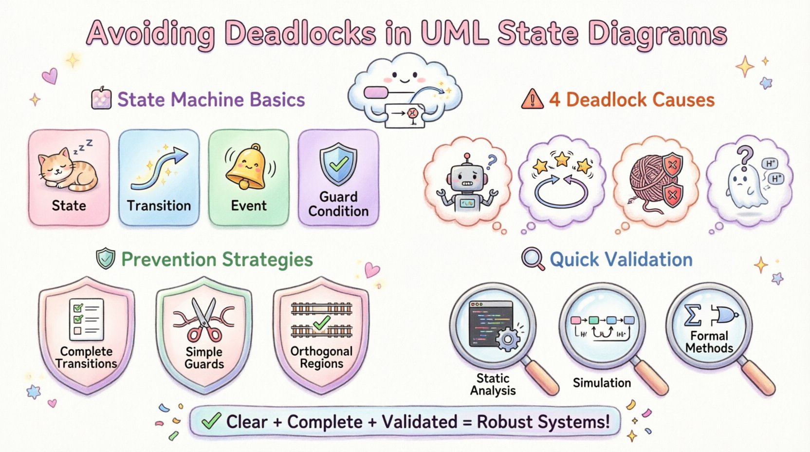
A state machine diagram models the behavior of a single object or a component over time. It defines states, transitions, events, and actions. The core principle is simple: an entity exists in one state at a time and moves to another based on specific conditions.
- State: A condition during the life of an object during which it satisfies some condition, performs some activity, or waits for some event.
- Transition: A relationship between two states indicating that objects in the source state will move to the target state when a specified event occurs.
- Event: A significant occurrence that triggers a transition.
- Guard Condition: A Boolean expression that must evaluate to true for the transition to occur.
When these elements are interconnected incorrectly, the model may describe a scenario where the system waits for an event that can never happen, or it enters a loop where no exit condition is met. This is the definition of a deadlock in the context of design.
⚠️ Common Causes of Deadlocks in Modeling
Deadlocks in UML diagrams usually stem from incomplete logic or conflicting constraints. The following list details the most frequent architectural errors.
1. Missing Transitions
Every state should ideally have a defined path for every possible event it can receive. If an event arrives in a state where no outgoing transition exists, the system may log an error or, depending on implementation, halt.
- Issue: A state has no outgoing arrows for a specific event type.
- Impact: Runtime exception or undefined behavior.
- Fix: Define a default transition or explicitly handle the event.
2. Circular Dependencies
Transitions often form cycles. While cycles are necessary for loops, they can become deadlocks if guard conditions prevent exit.
- Issue: State A transitions to State B, and State B transitions back to State A, but the guard conditions for both rely on a variable that never changes.
- Impact: The system spins indefinitely without progressing.
- Fix: Ensure at least one state in the cycle has an unconditional exit or a timeout mechanism.
3. Guard Condition Conflicts
Guard conditions are powerful tools for controlling flow, but they are also a source of complexity. If the conditions for all outgoing transitions from a state are mutually exclusive and never met, the state becomes a trap.
- Issue: Transition 1 requires
isReady == true. Transition 2 requiresisReady == false. The system logic setsisReadytonullbefore the event fires. - Impact: No transition fires; the system waits.
- Fix: Review the lifecycle of variables referenced in guards.
4. Improper Use of History States
History states allow a composite state to remember its last sub-state. Misusing deep history (*) versus shallow history (H) can lead to confusion about which state the system should re-enter, potentially causing logic loops.
🛡️ Prevention Strategies
Preventing deadlocks requires a proactive approach to modeling. The following strategies help ensure logical consistency and flow.
1. Enforce Transition Completeness
When drawing a diagram, perform a check for every state. For every event listed in the system context, is there a corresponding transition? If not, determine if the event is valid for that state.
- Use acceptance states to explicitly mark where a process ends successfully.
- Use error states to capture unexpected events and define a recovery path.
- Avoid silent failures; every path should lead somewhere.
2. Simplify Guard Conditions
Complex guard conditions are difficult to verify. If a transition requires three conditions to be met, the likelihood of an oversight increases.
- Rule of Thumb: Keep guards simple and testable.
- Refactoring: Move complex logic into entry/exit actions rather than transition guards where possible.
- Default Paths: Use a default transition (often drawn as a line without an event label) to catch unhandled cases.
3. Leverage Orthogonal Regions
For systems with concurrent behaviors, UML allows orthogonal regions (parallel states). This can prevent deadlocks caused by single-threaded logic trying to handle multiple independent concerns simultaneously.
- Split concerns: If a system needs to handle logging and processing independently, model them in separate regions.
- Event Broadcasting: Events in one region can trigger transitions in another without blocking the source region.
- Synchronization: Use synchronization bars to ensure both regions are ready before proceeding to a combined state.
📊 Scenario Analysis: Deadlock Patterns
The table below outlines common patterns found in state diagrams that lead to deadlocks, along with the recommended corrective actions.
| Pattern | Description | Consequence | Corrective Action |
|---|---|---|---|
| The Closed Loop | States A and B transition to each other with guards that depend on each other. | System oscillates without progress. | Introduce a timeout or a third state to break the cycle. |
| The Missing Handler | Event X occurs in State Y, but no arrow exists. | Unhandled exception or system freeze. | Add a generic error transition or explicitly discard the event. |
| The Impossible Guard | Guard condition 1 == 2 is written by mistake. |
Transition never fires. | Refactor logic to ensure guards are logically possible. |
| The Orphan State | A state has no incoming transitions. | State is unreachable; logic is dead code. | Remove the state or connect it via a valid entry point. |
| Double Final | Multiple final states with no synchronization. | Ambiguity in termination logic. | Consolidate to a single final state or ensure distinct termination paths. |
🔍 Validation and Verification Techniques
Designing a diagram is only the first step. Verification ensures the model behaves as intended before code is written.
1. Static Analysis
Use tools to check the model for structural integrity. Automated checkers can identify:
- States with no outgoing transitions for defined events.
- Cycles that lack exit conditions.
- Unreachable states.
2. Simulation and Tracing
Simulate the state machine with various input sequences. This helps visualize the flow of execution.
- Happy Path: Does the system complete successfully?
- Edge Cases: What happens if an event arrives out of order?
- Stress Testing: Can the system handle rapid event firing without queuing issues?
3. Formal Methods
For critical systems, formal verification techniques can mathematically prove that deadlocks are impossible. This involves modeling the system as a finite automaton and proving that no reachable state is a deadlock state.
🔄 Handling Concurrency and Parallelism
Concurrency introduces complexity. When multiple threads or processes interact with the state machine, deadlocks can occur at the synchronization level, not just the logical state level.
1. Event Queues
If events are queued, the order of processing matters. A deadlock can occur if State A waits for an event that State B is supposed to generate, but State B is waiting for State A to finish a task.
- Solution: Design non-blocking event processing where possible.
- Solution: Use timeouts to break wait loops.
2. Resource Locking
State transitions often involve acquiring resources. If transitions require locks in a specific order, circular lock dependencies can cause runtime deadlocks.
- Best Practice: Enforce a global ordering of resource acquisition.
- Best Practice: Minimize the scope of locks within transitions.
🛠️ Refactoring Existing Models
When working with legacy systems, state diagrams may be incomplete or poorly documented. Refactoring these models requires a systematic approach.
- Reverse Engineering: Extract the current logic from the code to build the initial diagram.
- Gap Analysis: Compare the diagram against the requirements. Identify missing transitions.
- Decomposition: Break large composite states into smaller, manageable units.
- Standardization: Apply consistent naming conventions for events and states.
- Documentation: Add comments to the diagram explaining complex guard conditions.
📝 Design Standards for Robustness
To maintain a healthy state machine ecosystem, adopt the following standards.
- Single Responsibility: A state should represent a single concept. If a state implies two different behaviors, split it.
- Explicit Transitions: Avoid implicit transitions. Every change in state should be visible in the diagram.
- Consistent Naming: Use verb-noun pairs for events (e.g.,
submitOrder,cancelRequest). - Clear Entry/Exit: Define
entryandexitactions clearly to manage side effects. - Version Control: Treat diagrams as code. Track changes to the model over time.
🔗 The Relationship Between Logic and Implementation
A state diagram is a specification, not the implementation itself. The logic defined in the model must be faithfully translated into code. Discrepancies between the model and the code are a primary source of runtime deadlocks.
Ensure that:
- The code implements the exact guard conditions defined in the diagram.
- The event handlers match the events in the model.
- State variables in the code match the state identifiers in the diagram.
Regular code reviews should include a check against the UML diagrams. This ensures that the implementation does not drift from the intended logic.
🏁 Final Thoughts on State Machine Integrity
Creating a deadlock-free system is a matter of rigorous design and continuous validation. By understanding the mechanics of transitions, guarding against circular logic, and maintaining strict standards, architects can build systems that remain responsive and reliable. The effort invested in modeling logic correctly pays dividends in reduced debugging time and increased system stability.
Remember that a state machine is a contract between the system and its environment. When that contract is clear, unambiguous, and complete, the system functions as intended. Focus on clarity, completeness, and validation to ensure your state diagrams serve as a foundation for robust software.