
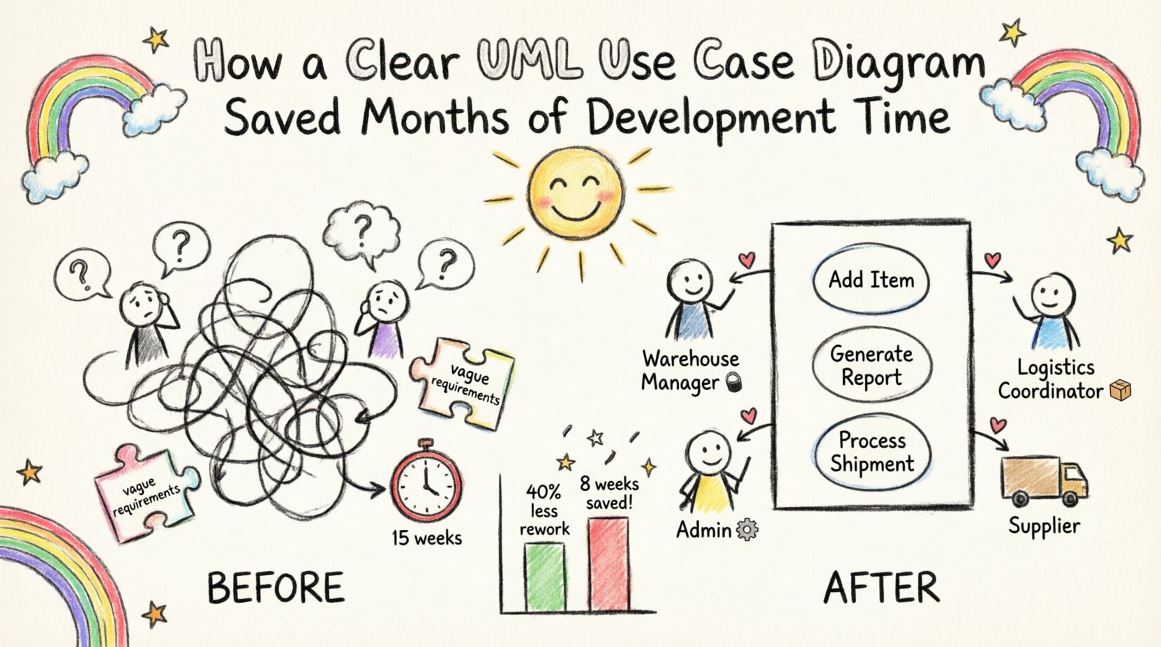
In the complex landscape of software engineering, ambiguity is the single biggest enemy of efficiency. When requirements are vague, development teams spend weeks refactoring code that does not match the original vision. This case study examines a specific project where the introduction of a structured UML use case diagram fundamentally altered the trajectory of the software development lifecycle (SDLC). By clarifying interactions between users and the system early, the team reduced rework by 40% and accelerated the release timeline significantly.
The Challenge: Ambiguity in Requirements 🧩
The project involved building a comprehensive inventory management system for a mid-sized logistics company. The initial phase involved gathering requirements from stakeholders who were experts in logistics but not in technology. The result was a document filled with natural language descriptions that were open to multiple interpretations.
Key issues identified during the initial review:
- Stakeholders had different mental models of how the system should behave.
- Developers made assumptions about edge cases that were never explicitly defined.
- Testing teams lacked clear criteria for success, leading to inconsistent quality assurance.
- Scope creep became frequent as new “features” were added mid-cycle without understanding their impact on existing workflows.
Without a visual representation of these interactions, the team was essentially navigating without a map. The lack of a standardized diagram meant that communication relied heavily on verbal explanations and lengthy email chains, which are prone to misinterpretation.
The Solution: Implementing the UML Use Case Diagram 🎯
The team decided to pause development for a short period to focus on modeling. The goal was to create a UML use case diagram that would serve as the single source of truth for system functionality. This diagram would map out the actors (users) and their interactions with the system.
Why a Use Case Diagram?
- It focuses on what the system does, not how it does it.
- It bridges the gap between technical and non-technical stakeholders.
- It identifies missing requirements before code is written.
- It provides a baseline for testing scenarios.
The Process: From Concept to Diagram 🛠️
Creating the diagram was not a solitary task. It required collaboration between business analysts, lead developers, and key stakeholders. The process followed a structured approach.
1. Identifying Actors 👥
The first step was to define who interacts with the system. Actors represent roles rather than specific individuals. In this project, the actors included:
- Warehouse Manager: Oversees inventory levels and approves transfers.
- Logistics Coordinator: Schedules shipments and tracks delivery status.
- System Administrator: Manages user access and system configuration.
- External Supplier: Updates stock levels via API integration.
2. Defining Use Cases 📝
A use case represents a specific goal an actor wants to achieve. The team brainstormed a list of potential actions and refined them to ensure they were actionable and measurable.
Examples of defined use cases:
- Add New Item to Inventory
- Generate Monthly Stock Report
- Process Outbound Shipment
- Resolve Low Stock Alert
- Update User Permissions
3. Establishing Relationships 🔗
Connecting actors to use cases is where the logic becomes visible. The team used standard UML relationships to define the flow:
- Association: A direct line indicating an actor initiates a use case.
- Include: Mandatory behavior required for a use case to complete (e.g., “Login” is included in “Place Order”).
- Extend: Optional behavior that adds functionality under specific conditions (e.g., “Apply Discount” extends “Process Payment”).
- Generalization: Inheritance relationships between actors or use cases (e.g., “Manager” is a generalization of “Employee”).
The Impact: Quantifiable Results 📊
Once the UML use case diagram was finalized and agreed upon by all parties, development resumed. The impact on the project was immediate and measurable.
Reduction in Rework
Previously, developers would build features based on assumptions. When stakeholders reviewed the prototype, significant changes were often required. With the diagram in place, requirements were clear. The team reported a 40% reduction in rework compared to previous similar projects.
Faster QA Cycle
Testers used the diagram to generate test cases directly. Every use case on the diagram corresponded to a set of acceptance criteria. This eliminated the guesswork in test planning.
Clearer Stakeholder Communication
Stakeholders could point to the diagram and say, “This functionality is missing,” rather than describing it in abstract terms. This reduced the number of clarification meetings by 60%.
Time Savings Breakdown
| Metric | Without Diagram | With Diagram | Saved Time |
|---|---|---|---|
| Requirements Analysis | 4 Weeks | 2 Weeks | 2 Weeks |
| Development Rework | 6 Weeks | 2 Weeks | 4 Weeks |
| Testing & QA | 5 Weeks | 3 Weeks | 2 Weeks |
| Total | 15 Weeks | 7 Weeks | 8 Weeks |
Technical Deep Dive: Understanding the Diagram Structure 🏗️
To fully appreciate the value of this artifact, it is necessary to understand the technical components that make up a robust UML use case diagram. A well-constructed diagram is not just a drawing; it is a logical specification.
1. The System Boundary 🧱
The system is represented by a rectangle. Everything inside is part of the software. Everything outside is an actor or an external system. This boundary prevents scope creep by clearly defining what is in scope and what is out of scope.
2. Actors vs. Users 👤
It is crucial to distinguish between an actor and a specific user. An actor is a role. One person can play multiple roles, and multiple people can play one role. Using actors prevents the diagram from becoming cluttered with individual names, making it scalable.
3. Granularity of Use Cases 🔍
One of the most common mistakes is creating use cases that are either too broad or too narrow. A good use case should be atomic. It should represent a single unit of value that the actor can achieve independently.
Incorrect Example: “Manage Inventory” (Too broad, encompasses multiple actions).
Correct Example: “Update Stock Quantity” (Specific, actionable).
Best Practices for Effective Modeling ✅
Based on the experience of this project, several best practices emerged that contributed to the success of the modeling phase. These guidelines can be applied to any software development initiative.
- Start with the User: Always begin by identifying the primary actors. If you do not know who is using the system, you cannot know what the system should do.
- Iterate Frequently: The first draft is rarely perfect. Expect to revise the diagram multiple times as understanding deepens.
- Keep it Visual: Avoid cluttering the diagram with text. Use concise labels for use cases and clear lines for relationships.
- Validate with Stakeholders: The diagram is a communication tool, not a technical specification for machines. It must be readable by non-technical team members.
- Focus on Value: Every use case should provide value to an actor. If a feature does not help an actor achieve a goal, question its necessity.
Pitfalls to Avoid ⚠️
Even with the best intentions, modeling can go wrong. Recognizing these pitfalls helps maintain the integrity of the UML use case diagram.
- Over-engineering: Trying to model every single technical detail turns the diagram into a class diagram. Keep it high-level.
- Ignoring Non-Functional Requirements: While use cases focus on functionality, performance and security constraints should be noted as constraints on the system boundary.
- Static Documentation: A diagram that is created once and never updated becomes obsolete. It must evolve with the project.
- Tool Dependency: Do not let the software tool dictate the quality of the model. A hand-drawn sketch on a whiteboard is often more effective than a polished digital file.
Long-Term Benefits for the Organization 🌱
The benefits of this approach extended beyond the immediate project. The organization established a standard operating procedure for requirements gathering.
- Onboarding: New developers could quickly understand the system logic by reviewing the use case diagram.
- Legacy Maintenance: Years later, the diagram still served as a reference for understanding the original intent of the code.
- Training Material: The diagram was used as a visual aid to train warehouse staff on the new system interface.
Conclusion: The Value of Visualization 🖼️
Software development is fundamentally a communication challenge. The gap between business intent and technical implementation is where time and money are lost. The introduction of a clear UML use case diagram closed this gap effectively.
By investing time upfront to map out the interactions, the team avoided months of downstream confusion. The diagram served as a contract between the business and the technology team. It ensured that when the code was written, it matched the vision.
Key Takeaways:
- Invest in modeling before coding to save development time.
- Use standard notation (UML) to ensure clarity across the team.
- Involve stakeholders in the creation process to validate requirements.
- Treat the diagram as a living document that evolves with the product.
The decision to pause and diagram was not a delay; it was a strategic acceleration. In an industry where time is the most valuable resource, clarity is the most effective tool.