
Creating a UML Use Case Diagram is a fundamental step in defining the functional scope of a software system. It serves as a visual contract between stakeholders, business analysts, and developers. However, a diagram drawn without rigorous validation often leads to ambiguity, scope creep, and implementation errors later in the development lifecycle. This guide provides a comprehensive technical framework to validate UML Use Case Diagrams specifically during the requirements gathering phase. The focus is on structural integrity, functional completeness, and alignment with business goals.
🎯 1. Preparing the Groundwork: Actor Identification
The foundation of any Use Case Diagram lies in the actors. An actor represents a role played by an entity that interacts with the system. Validation begins here because incorrect actor definitions can render the entire diagram meaningless.
- External vs. Internal: Distinguish clearly between actors outside the system boundary and internal processes. An actor should typically represent a human user, a hardware device, or another system. Internal database processes are usually not actors unless they are explicitly triggered by an external request.
- Role-Based Definitions: Ensure actors are defined by their role, not by a specific job title. For example, use “Manager” instead of “John Smith”. This ensures the diagram remains valid even if personnel change.
- Interaction Direction: Verify that the direction of interaction is correct. Does the actor initiate the action, or does the system notify the actor? The arrow should point from the initiator to the target use case.
- Passive vs. Active: Identify if the actor is passive (e.g., receiving a notification) or active (e.g., initiating a transaction). This affects how the use case is described in the text requirements.
- Exclusion of System: The system itself should never be an actor. The system is the context, not the participant.
🛠️ 2. Defining the Use Cases: Goals and Scope
A use case represents a complete unit of functionality. It must describe a specific goal that an actor wants to achieve. Validation of use cases requires checking for atomicity and clarity.
- Goal-Oriented: Every use case must correspond to a specific business goal. If a use case is merely a step in a larger process (e.g., “Click Button”), it is likely too granular. It should be elevated to a higher-level goal (e.g., “Submit Application”).
- Active Voice: Use cases should be named in the active voice. “Login” is better than “Login by User”. The name should imply the actor without explicitly stating it in the label.
- Atomicity: Ensure each use case represents a single, distinct capability. Avoid combining multiple unrelated actions into one bubble. If a use case can be split into two distinct goals, split it.
- Completeness: Does every use case have a clear start and end? The diagram should reflect the full flow, not just the happy path. Consider alternative flows that might be represented through extensions later.
- Consistency in Naming: Maintain a consistent naming convention across the diagram. If you use verbs for some use cases (e.g., “Generate Report”), do not use nouns for others (e.g., “Report Generation”).
🔗 3. Mapping Relationships: Connectors and Logic
The lines connecting actors and use cases, and use cases to other use cases, carry semantic meaning. Misinterpreting these relationships is a common source of validation failure.
- Association Lines: These connect actors to use cases. They indicate that the actor participates in the use case. Ensure there are no dangling lines or connections to non-existent actors.
- Include Relationship: This denotes mandatory behavior. If Use Case A includes Use Case B, Use Case B must happen every time Use Case A is executed. Validate that this is truly mandatory and not optional.
- Extend Relationship: This denotes optional or conditional behavior. Use Case A extends Use Case B only under specific conditions. Ensure the base use case (B) is valid on its own without the extension (A).
- Generalization (Inheritance): This represents a “is-a” relationship between actors or between use cases. A child actor should be able to perform all functions of the parent actor. Validate that the inheritance hierarchy makes logical sense and isn’t just a shortcut for copying lines.
- Avoid Cycles: Ensure there are no circular dependencies between use cases (e.g., A includes B, and B includes A). This creates an infinite loop in logic and is invalid.
🚧 4. The System Boundary: Scope and Containment
The rectangle representing the system boundary defines what is inside the system and what is outside. This is crucial for defining the scope of the project.
- Internal Use Cases: All use cases must be contained within the system boundary. If a use case is partially inside and partially outside, the boundary is incorrectly drawn.
- External Actors: Actors must always be placed outside the system boundary. If an actor is inside, it implies the actor is part of the system’s internal logic.
- Boundary Clarity: The boundary should clearly separate the system from its environment. This helps stakeholders understand what the system is responsible for and what is external.
- Interface Points: The boundary line acts as the interface. Ensure all interactions cross this line. If an actor connects directly to another actor without crossing the boundary, it implies a direct system-to-system interaction that might need clarification.
📝 5. Consistency with Textual Requirements
A Use Case Diagram is a high-level abstraction. It must align perfectly with the detailed textual requirements. Discrepancies here lead to development errors.
- Traceability: Every use case on the diagram should have a corresponding entry in the requirements document. Conversely, every critical functional requirement should be represented on the diagram.
- Granularity Match: If the text describes a complex workflow involving multiple steps, ensure the diagram reflects the high-level steps correctly. Don’t map low-level UI actions to use cases.
- Constraint Alignment: Check if the diagram reflects any constraints mentioned in the text. For example, if the text says “Only Admins can delete,” ensure the “Delete” use case is only connected to the “Admin” actor.
- Terminology: The names used in the diagram must match the terminology used in the business requirements. This prevents confusion during the development phase.
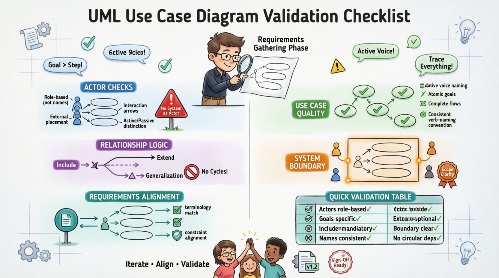
📊 6. Validation Checklist Summary
The following table summarizes the critical validation points. Use this as a quick reference during the review process.
| Category | Validation Question | Pass Criteria |
|---|---|---|
| Actors | Are all actors defined by role? | Yes, no specific names used. |
| Actors | Are actors outside the boundary? | Yes, no actors inside the box. |
| Use Cases | Are use cases goal-oriented? | Yes, each achieves a specific goal. |
| Relationships | Are Include/Extend relationships correct? | Yes, Include is mandatory, Extend is optional. |
| Boundary | Is the system boundary clear? | Yes, contains all use cases, excludes actors. |
| Traceability | Does it match requirements text? | Yes, one-to-one mapping exists. |
| Clarity | Are names consistent? | Yes, active voice, consistent naming. |
| Logic | Are there circular dependencies? | Yes, no loops in relationships. |
🚫 7. Common Validation Errors and Fixes
Understanding common pitfalls helps in avoiding them during the initial drafting phase. The table below outlines frequent errors and the corrective actions required.
| Error Type | Description | Correction Strategy |
|---|---|---|
| Actor Inside Boundary | An actor is drawn inside the system box. | Move the actor outside the boundary. |
| System as Actor | The system itself is listed as an actor. | Remove the system from the actor list. |
| UI Elements | Use cases are named like screens or buttons. | Rename to reflect the business goal (e.g., “View Screen” → “Display Dashboard”). |
| Missing Actors | A use case has no actor connected to it. | Identify the initiating actor or remove the orphaned use case. |
| Over-Abstraction | Use cases are too vague (e.g., “Manage System”). | Break down into specific functional goals. |
| Over-Granularity | Too many small steps mapped as use cases. | Group steps into a single logical goal. |
| Inconsistent Extensions | Extends are used where Includes are needed. | Review the logic: Is the behavior optional? If yes, Extend. If no, Include. |
🧩 8. Reviewing Granularity and Abstraction Levels
One of the most challenging aspects of validation is determining the correct level of detail. The diagram must be high enough to see the scope, but detailed enough to be useful.
- High-Level View: For executive stakeholders, the diagram should show major capabilities without diving into sub-processes. This is often called the “Level 1” diagram.
- Mid-Level View: For project managers and developers, the diagram should include Include and Extend relationships to show dependencies.
- Low-Level View: Detailed logic for specific use cases should be documented in Use Case Specifications, not on the main diagram. Do not clutter the diagram with flow details.
- Iterative Refinement: Validation is not a one-time event. As requirements evolve, the diagram must be updated. Ensure the abstraction level remains appropriate for the current phase of development.
- Contextual Relevance: A use case valid for a backend service might not be visible in a user-facing diagram. Ensure the diagram matches the context of the audience reviewing it.
🤝 9. Stakeholder Alignment and Sign-Off
Validation is not just a technical exercise; it is a communication tool. The diagram must be understood by the people who will approve the requirements.
- Stakeholder Review: Present the diagram to business stakeholders. Ask them if the diagram reflects their understanding of how the business works.
- Developer Feedback: Consult with lead developers. They can identify technical constraints that might make certain use cases impossible or require significant refactoring.
- Consensus Building: If stakeholders disagree on a use case’s scope, use the diagram as a neutral ground to discuss boundaries. Visualizing the conflict often resolves it faster than text.
- Sign-Off Criteria: Define what constitutes a valid diagram before starting. For example, “No orphaned actors” and “All critical requirements mapped” should be prerequisites for sign-off.
- Version Control: Treat the diagram as a living document. Record changes made during validation. This ensures traceability if requirements drift later.
🔍 10. Final Technical Considerations
Beyond the visual elements, there are technical constraints to consider when validating the diagram’s structure.
- Naming Conventions: Ensure all elements follow the organization’s standard naming convention. This aids in automated tooling and documentation generation later.
- Tool Compatibility: If the diagram is created in a specific modeling tool, ensure it exports correctly to other formats if needed. Avoid proprietary features that lock the diagram into one platform.
- Scalability: Consider if the diagram will remain valid as the system grows. Avoid hard-coding specific data values or temporary configurations into the use case names.
- Security Context: Ensure that security constraints are implied or noted. For example, if a use case requires authentication, the actor should be able to prove their identity. This doesn’t need a separate use case but must be clear.
- Non-Functional Requirements: While Use Case Diagrams focus on functionality, consider if performance or availability requirements impact the scope. If a use case is too heavy for the system, it might need to be split or redesigned.
Validating a UML Use Case Diagram is an iterative process that demands attention to detail and a deep understanding of the system’s purpose. By adhering to this checklist, teams can ensure that their visual models accurately reflect the requirements, reducing the risk of costly rework during the implementation phase. The goal is clarity, precision, and alignment.