
Creating a Use Case Diagram is often the first step a system analyst or developer takes to visualize the functional requirements of a software system. It acts as a bridge between technical implementation and business goals. However, many newcomers struggle with the nuances of this modeling technique. Missteps in this diagramming process can lead to confusion later in development, scope creep, or missing critical functionality.
This guide explores the most frequent errors found in UML Use Case Diagramming. We will examine why these mistakes occur and provide concrete strategies to correct them. By understanding the underlying logic of actor interactions and system boundaries, you can create diagrams that are accurate, maintainable, and useful for stakeholders.
Understanding the Core Components 🧩
Before diving into the mistakes, it is essential to define the building blocks of a valid Use Case Diagram. A diagram without a clear foundation is prone to structural failure. The standard elements include:
- Actors: Represented as stick figures, these are external entities interacting with the system. They can be human users, other systems, or hardware devices.
- Use Cases: Represented as ovals, these describe a specific function or service the system provides to an actor.
- System Boundary: A rectangle that encloses the use cases, defining what is inside the system and what is outside.
- Relationships: Lines connecting actors to use cases or use cases to other use cases.
Each element serves a distinct purpose. When you mix these roles, the diagram loses its semantic meaning. For instance, treating a process as an actor changes the scope of the model entirely.
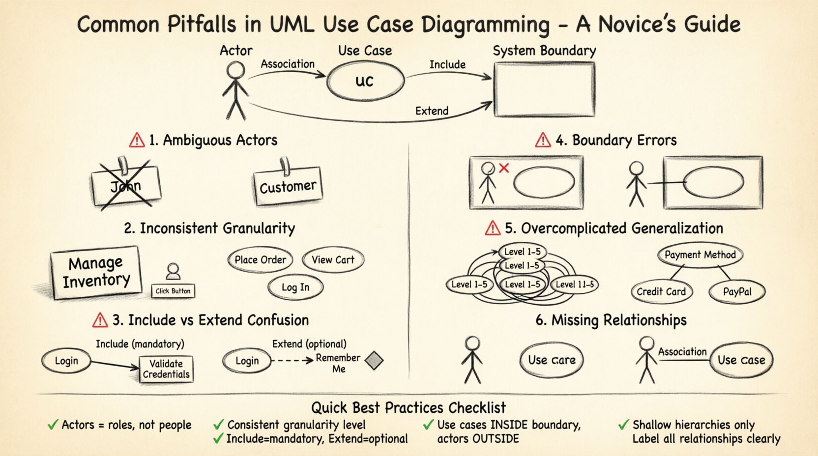
Pitfall 1: Ambiguous Actor Definitions 🤔
One of the most common issues beginners face is defining actors incorrectly. An actor is defined as an external entity that interacts with the system. However, novices often confuse specific roles within an organization with the actor itself.
The Mistake
Creating an actor named “John” or “Manager” based on a specific person or a specific department name. This ties the model to a specific instance rather than a role.
The Consequence
When the person named “John” leaves the company, the model requires updating. Furthermore, if a different person takes the “Manager” role but has different permissions, the diagram fails to represent the variance.
The Solution
Use generic role names. Instead of “John Smith,” use “Customer” or “Administrator.” Instead of “Sales Department,” use “Sales Representative.” This ensures the model remains valid regardless of personnel changes.
- ✅ Correct: Actor = “Registered User”
- ❌ Incorrect: Actor = “David from Marketing”
Additionally, ensure actors are truly external. If an entity is inside the system and performs internal logic, it should not be an actor. Actors initiate the interaction from outside the system boundary.
Pitfall 2: Inconsistent Granularity 📏
Granularity refers to the level of detail in your use cases. A diagram must maintain a consistent level of abstraction throughout. Mixing high-level goals with low-level technical steps creates confusion.
The Mistake
Combining broad business goals with specific interface clicks in the same diagram. For example, having “Manage Inventory” alongside “Click Submit Button.”
The Consequence
The diagram becomes cluttered and unreadable. Stakeholders looking for business value see unnecessary technical details. Developers looking for technical specs get lost in high-level business goals.
The Solution
Adopt a standard granularity level. A good rule of thumb is to define use cases based on the value delivered to the actor. If the actor perceives the action as a single goal, it is likely a valid use case.
- High Level: “Place Order” (Entire process)
- Mid Level: “Add Item to Cart” (Specific action)
- Low Level: “Validate Credit Card” (Technical validation)
For a standard Use Case Diagram, the Mid Level is usually the sweet spot. If you find yourself listing technical validations, consider moving them to a separate detailed specification or a sequence diagram.
Pitfall 3: Confusing Include and Extend Relationships 🔄
Relationships between use cases are powerful tools for managing complexity. However, the include and extend relationships are frequently misused. They serve different logical purposes.
The Mistake
Using include for optional behavior or using extend for mandatory behavior. Novices often swap these because they seem similar syntactically.
The Consequence
The logic of the system becomes unclear. A mandatory step being marked as extend implies it might not happen, which is risky for system integrity. An optional step marked as include implies it is always required.
The Solution
Follow the strict definitions:
- Include (<<include>>): Used when a use case must use the behavior of another use case. It is a mandatory dependency.
- Extend (<<extend>>): Used when a use case may add behavior to another use case under specific conditions. It is optional.
Here is a comparison table to clarify the differences:
| Feature | Include Relationship | Extend Relationship |
|---|---|---|
| Dependency | Mandatory | Optional |
| Direction | From Base to Included | From Extension to Base |
| Trigger | Always triggered | Triggered by condition |
| Example | “Login” includes “Validate Password” | “Login” extends “Show Welcome Message” (if valid) |
When modeling, ask yourself: Does this step happen every time? If yes, use include. Does it happen only sometimes? If yes, use extend.
Pitfall 4: Ignoring System Boundaries 🧱
The system boundary is the rectangle that separates the system from the outside world. It defines the scope of your project. Novices often draw actors inside the boundary or place use cases outside of it.
The Mistake
Placing actors (users) inside the rectangle or placing use cases (functions) outside the rectangle.
The Consequence
This violates the fundamental definition of a Use Case Diagram. It becomes impossible to determine what the system is responsible for versus what is the responsibility of the environment. Communication with developers becomes difficult because the scope is blurred.
The Solution
Ensure all use cases are contained within the rectangle. Ensure all actors are outside the rectangle. The lines (associations) should cross the boundary.
- Inside: All system functions (Use Cases).
- Outside: All users and external systems (Actors).
- Crossing: The interaction lines.
If you have multiple systems interacting, you may use multiple rectangles, but the actor must remain external to the specific system being modeled.
Pitfall 5: Overcomplicating with Generalization 🌳
Generalization allows you to create hierarchies among actors and use cases. For example, “Admin” is a type of “User.” While powerful, novices often overuse this feature.
The Mistake
Creating deep inheritance trees that are hard to read. For example, having “User” extend to “Guest User” which extends to “Registered Guest User.”
The Consequence
The diagram becomes a maze. Stakeholders struggle to understand the inheritance logic. The diagram loses its value as a high-level overview.
The Solution
Use generalization only when it adds significant clarity. Usually, one level of hierarchy is sufficient. If you find yourself needing three levels of inheritance, consider simplifying the actor roles or breaking the diagram into sub-diagrams.
- Keep the hierarchy shallow.
- Focus on behavioral differences rather than identity differences.
- Use generalization for permissions that differ significantly.
Pitfall 6: Missing or Unclear Relationships 🚫
Association lines are the primary way actors interact with the system. However, sometimes these lines are missing, or they are drawn between two use cases incorrectly.
The Mistake
Connecting an actor to a use case that they do not actually initiate. Or connecting two use cases without a relationship type (include/extend).
The Consequence
False functionality is implied. If a line exists, it implies an interaction. If the interaction is not valid, the diagram promises features that do not exist.
The Solution
Review every line. Ask: Does this actor actually start this process? If the answer is no, remove the line. If two use cases are related, define the relationship type explicitly. Do not leave lines unlabelled unless they are simple associations.
Best Practices Checklist ✅
To ensure your diagrams are robust and professional, review them against this checklist before finalizing.
- Scope Check: Are all use cases inside the system boundary?
- Actor Check: Are all actors outside the system boundary?
- Role Check: Are actors named by role, not by person?
- Granularity Check: Is every use case a single goal for the actor?
- Relationship Check: Are include/extend relationships used correctly?
- Completeness Check: Does every actor have at least one interaction?
- Clarity Check: Are labels clear and concise?
Reviewing Your Diagrams 🧐
Once the diagram is drawn, the work is not done. Validation is a critical phase. You should review the diagram with stakeholders. Ask them to walk through the scenarios. Does the diagram match their mental model of how the system should work?
During the review, look for:
- Redundancy: Are there two use cases doing the same thing?
- Gaps: Are there missing steps in a critical flow?
- Complexity: Is the diagram too crowded to read?
If the diagram is too crowded, consider splitting it. You can create a “Main Flow” diagram and a “Detail” diagram for specific complex modules. This modular approach keeps the main overview clean.
Technical Consistency and Standards 📐
Adhering to UML standards ensures that anyone familiar with the methodology can read your diagram. Deviating from standard notations creates friction.
- Actor Icon: Always use the stick figure. Do not use images or icons for actors.
- Use Case Icon: Always use the oval. Do not use rounded rectangles.
- Text: Use verb-noun phrases for use cases (e.g., “Process Payment” not “Payment”).
- Lines: Use solid lines for associations. Use dashed lines with stereotypes for include/extend.
Consistency reduces the learning curve for new team members. It also reduces errors during the handoff to developers.
Common Edge Cases 🎲
There are specific scenarios that often trip up modelers. Handling these correctly demonstrates a deep understanding of the notation.
External Systems as Actors
When another software system interacts with yours, it is an actor. Do not put the other system inside your boundary. Draw it as an external entity. This clarifies that the interaction is a system-to-system interface.
Time-Based Actors
Sometimes a system triggers an action based on time, like a nightly backup. In this case, the actor can be a “Scheduled Trigger” or “Time Interval.” This is a valid actor type representing a non-human trigger.
Sub-Systems
If a large system is divided into sub-systems, you can model the top-level system and then create detailed diagrams for each sub-system. This is known as hierarchical modeling. It prevents a single diagram from becoming too large to manage.
Final Thoughts on Model Accuracy 🎯
The goal of a Use Case Diagram is not just to draw shapes. It is to communicate intent. Accuracy is more important than aesthetic perfection. A diagram that is technically correct but hard to read is useless. A diagram that is slightly simplified but clearly conveys the flow is valuable.
By avoiding the pitfalls outlined in this guide, you ensure that your models serve as reliable documentation. You save time during development by preventing scope misunderstandings. You provide a clear contract between the business requirements and the technical solution.
Remember that modeling is an iterative process. As requirements change, your diagram should change with them. Keep the documentation alive by updating it as the system evolves. This maintains its value as a reference point for the entire project lifecycle.