
Activity diagrams are a fundamental component of modeling complex business processes and software workflows. They provide a visual representation of the dynamic behavior within a system. However, as processes grow in complexity, a standard flow chart can become a tangled web of logic. This is where swimlanes become essential. Swimlanes introduce a layer of organization that separates actions by responsibility, owner, or system. This guide explores how to effectively utilize swimlanes to clarify accountability and streamline process visualization.
What Are Swimlanes in Activity Diagrams? 🧭
A swimlane is a visual partition within an activity diagram. It divides the diagram into distinct zones, where each zone represents a specific category of responsibility. This structure allows readers to instantly see who or what is performing a specific action. The concept borrows from the metaphor of a swimming pool, where lanes separate swimmers to avoid collisions and ensure order.
- Horizontal Swimlanes: These typically represent organizational units, departments, or roles. They run from left to right across the diagram.
- Vertical Swimlanes: These often represent system components, physical locations, or distinct systems. They run from top to bottom.
By segregating activities into these lanes, the diagram transforms from a simple sequence of events into a matrix of actions and owners. This distinction is critical for understanding process handoffs and dependencies.
Key Benefits of Using Swimlanes 📊
Implementing swimlanes in your activity diagrams offers several tangible advantages for stakeholders and developers. It moves the focus from what happens to who does it.
1. Clear Accountability 🙋♂️
Every activity box sits within a specific lane. If a step is unclear regarding ownership, the diagram becomes ambiguous. Swimlanes force the modeler to assign an owner to every step. This reduces the gray areas where tasks might fall through the cracks in a real-world implementation.
2. Identification of Handoffs 🔄
Complex processes often involve multiple departments or systems. A handoff occurs when an activity moves from one swimlane to another. Swimlanes make these transitions visually distinct. You can easily count the number of handoffs, which is a strong indicator of process complexity and potential friction points.
3. Bottleneck Detection 🚧
When a specific swimlane contains a high density of activities compared to others, it may indicate a workload imbalance. If one department is responsible for the majority of the steps in a flow, they may become a bottleneck. Visualizing this early allows for resource reallocation.
4. Reduced Cognitive Load 🧠
Without swimlanes, a long process flow can become difficult to trace. The eye must jump across the entire width of the diagram repeatedly. Swimlanes guide the reader’s eye horizontally or vertically, creating a natural reading path. This makes the diagram easier to scan and understand.
Types of Swimlane Classifications 🏷️
Not all swimlanes are created equal. Depending on the modeling context, you might categorize your lanes differently. Choosing the right classification depends on the audience and the specific problem you are solving.
| Type | Definition | Best Use Case |
|---|---|---|
| Organizational | Represents departments, teams, or job roles. | Business process mapping, HR workflows. |
| System | Represents software modules, databases, or hardware. | Technical architecture, API integration flows. |
| Process | Represents stages or phases of a project. | Project management, lifecycle modeling. |
| Resource | Represents specific assets or tools required. | Inventory management, equipment scheduling. |
Design Principles for Effective Swimlanes 🛠️
Creating a swimlane diagram requires adherence to specific design principles to ensure it remains readable and useful. Poor design can negate the benefits of the structure.
1. Limit the Number of Lanes
While granularity is good, too many lanes create a cluttered chart. If you find yourself needing more than 5 to 7 lanes, consider sub-dividing the diagram or creating a hierarchical model. A wide diagram with many thin lanes is harder to print and view than a focused one.
2. Consistent Flow Direction
Standard convention suggests activity flows from left to right or top to bottom. Swimlanes should align with this flow. Do not mix horizontal and vertical swimlanes within the same diagram unless absolutely necessary for specific architectural reasons. Consistency aids comprehension.
3. Naming Conventions
Labels for swimlanes must be concise and unambiguous. Avoid acronyms that not all stakeholders understand. Use standard job titles or system names. If a lane represents a role, use the singular form (e.g., “Customer” instead of “Customers”) to denote the actor type.
4. Crossing Boundaries
Transitions between swimlanes should be minimized. If an activity requires a transition, ensure the connector line is clean. Avoid lines that crisscross other lines unnecessarily. Use control nodes (fences) to manage the flow crossing boundaries cleanly.
Handling Complex Logic Within Lanes 🔗
Swimlanes do not restrict the complexity of the logic within them. You can still use decision nodes, forks, and joins inside a single lane. However, the organization changes how these nodes are interpreted.
Decision Nodes
A decision diamond inside a lane represents a choice made by that specific actor or system. For example, a decision node in the “Bank” lane represents a check performed by the bank’s automated system. It is crucial to ensure that the outgoing branches from a decision node return to the same lane unless a handoff is explicitly required.
Fork and Join Nodes
Forks split a single flow into parallel flows. If a fork splits a flow into two parallel paths, both paths should ideally start in the same lane. If one path requires a different system to execute, the fork point itself should be at the boundary or the split should be immediately followed by a transition to the new lane. Join nodes must consolidate flows back into a single path, often requiring a handoff back to the original lane or a merge into a subsequent process step.
Common Mistakes to Avoid ⚠️
Even experienced modelers can introduce errors that reduce the utility of a swimlane diagram. Being aware of these pitfalls helps maintain high standards.
- Orphaned Activities: Ensure every activity box is inside a swimlane. Activities floating outside a lane suggest an undefined owner or system.
- Overlapping Responsibilities: Avoid placing the same logical step in two different lanes. An action should have a single source of truth regarding who performs it.
- Ignoring Feedback Loops: Complex processes often require error handling or rework. Ensure that error paths are drawn clearly, even if they loop back into the same swimlane.
- Inconsistent Symbol Usage: Maintain standard notation for start/end states, activities, and control nodes. Inconsistency confuses the reader.
- Too Many Cross-Lane Transitions: If the diagram looks like a spiderweb of lines crossing between lanes, the process is likely too fragmented. Consider grouping steps to minimize boundary crossings.
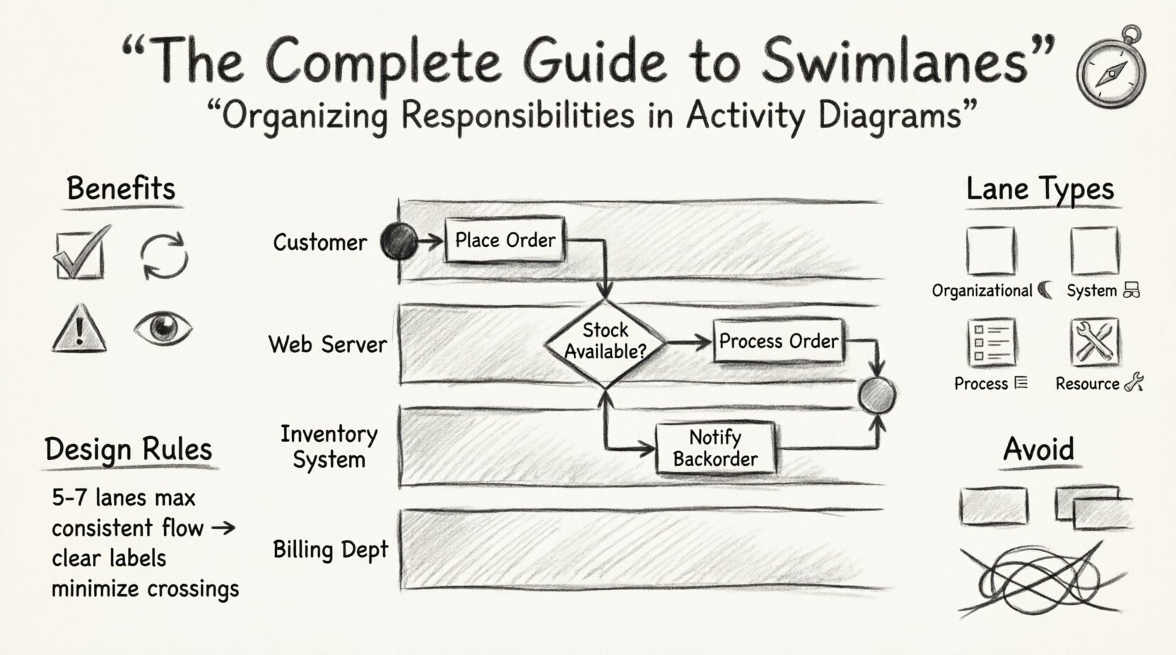
Case Study: Order Processing Workflow 📦
To illustrate the practical application of swimlanes, consider a standard order processing workflow. Without swimlanes, the steps might look like a long list. With swimlanes, we can see the interaction between the Customer, the Web Server, the Inventory System, and the Billing Department.
Scenario Breakdown
Let us analyze the flow of a purchase order:
- Customer Lane: Initiates the request, provides shipping details, confirms payment.
- Web Server Lane: Validates input, checks session status, routes to inventory.
- Inventory System Lane: Checks stock levels, reserves items, updates database.
- Billing Department Lane: Generates invoice, processes payment transaction, sends confirmation.
In this structure, the Inventory System lane acts as a gatekeeper. If stock is unavailable, the flow returns to the Customer lane with a notification. This loop is visually contained within the boundaries of the respective lanes, making the logic easy to trace.
Integration with Other Modeling Techniques 🧩
Swimlanes in activity diagrams are not isolated. They often interact with other diagrams in the modeling ecosystem.
Use Case Diagrams
Use case diagrams identify what the system does from a user perspective. Activity diagrams with swimlanes explain how those functions are executed internally. A single use case might trigger an activity diagram with multiple swimlanes representing backend processing.
Sequence Diagrams
Sequence diagrams focus on the timing and order of messages between objects. Swimlane activity diagrams focus on the logic and ownership of the actions. They complement each other: the sequence diagram details the specific message exchange, while the swimlane diagram provides the high-level process context.
State Machine Diagrams
State machines track the status of an object. Swimlanes track the status of a process. In complex systems, a state machine might reside within a specific swimlane to track the lifecycle of a single entity, while the activity diagram tracks the overall workflow.
Best Practices for Maintenance 🔄
A diagram is a living document. As processes evolve, the diagram must evolve with them. Maintaining swimlane diagrams requires discipline.
- Version Control: Keep track of changes. If a process changes ownership, update the lane assignment immediately.
- Review Cycles: Have stakeholders from each lane review the diagram. The “Billing Department” should verify that the activities in their lane accurately reflect their reality.
- Update Frequency: Set a schedule for review. Quarterly reviews are common for critical business processes.
- Documentation: Add annotations to explain complex logic within a lane. Do not rely solely on the visual flow.
Technical Considerations for Implementation 💻
When modeling these diagrams in a technical environment, keep the following constraints in mind.
- Scalability: Large diagrams can become difficult to render. Consider breaking a large process into sub-processes. Use a master swimlane diagram that calls into detailed swimlane diagrams for specific sections.
- Tool Limitations: Some older tools struggle with deep nesting of swimlanes. Stick to flat structures where possible to ensure compatibility with all viewing platforms.
- Export Formats: Ensure your diagrams export to formats like PDF or SVG that preserve the lane boundaries clearly. Vector graphics are preferred for scaling without loss of clarity.
Conclusion 🏁
Swimlanes provide a structured approach to organizing responsibilities within activity diagrams. They transform abstract flows into actionable maps of ownership and execution. By clearly defining who performs each step, teams can reduce ambiguity, identify bottlenecks, and improve communication.
When applied correctly, with attention to naming, lane limits, and transition clarity, swimlane diagrams become a powerful asset in business analysis and system design. They bridge the gap between high-level requirements and detailed implementation logic. As you continue to model processes, prioritize clarity and accountability in every lane you draw.