
Understanding how software behaves under different conditions is critical for building robust systems. One of the most effective ways to visualize this behavior is through a Unified Modeling Language (UML) State Diagram, often referred to as a State Machine Diagram. For new developers, these diagrams can initially appear complex, but they represent a structured method for modeling the dynamic behavior of a system.
This guide provides a deep dive into every essential component. We will explore the syntax, semantics, and practical applications without relying on specific tools or products. By the end of this article, you will have a clear mental model of how states, transitions, and actions interact to define system logic.
🏁 What Is a UML State Diagram?
A UML State Diagram is a behavioral diagram that shows the discrete conditions under which an object exists and the events that cause it to change from one condition to another. It answers questions like:
- What can the system do? (The available states)
- What triggers a change? (The events)
- What happens during a change? (The actions)
Unlike an Activity Diagram, which focuses on the flow of control from activity to activity, a State Diagram focuses on the lifecycle of a specific object or component. It is particularly useful for:
- Complex business logic workflows
- Protocol implementation (e.g., network handshakes)
- Game character states (idle, running, jumping)
- Device lifecycle management (boot, operating, shutdown)
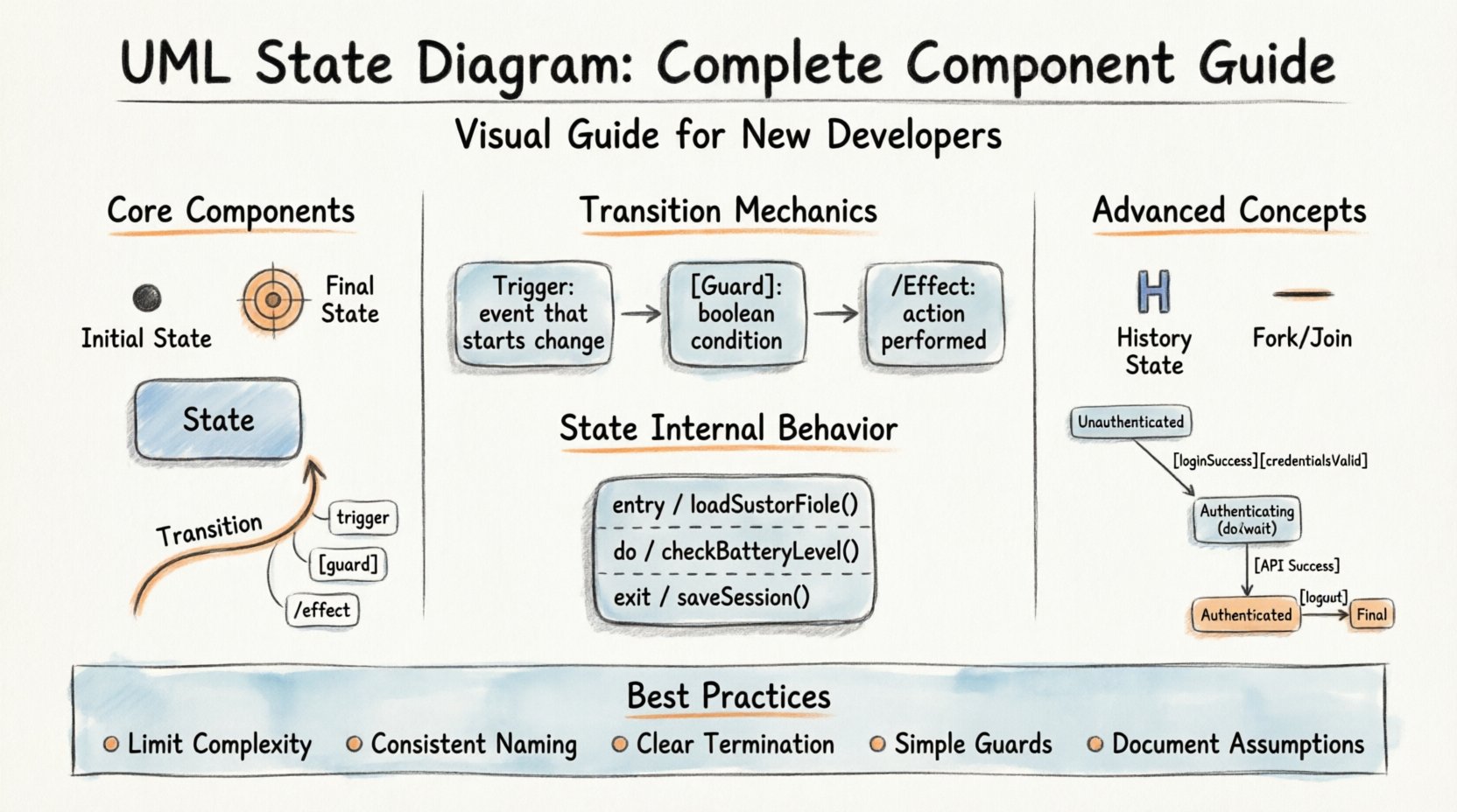
🧱 Core Structural Components
Every state diagram is built upon a foundation of specific graphical elements. Below is a breakdown of the primary building blocks you will encounter.
1. Initial State 🔴
The Initial State represents the starting point of the state machine. It is where execution begins when the object is created.
- Visual Symbol: A solid black circle.
- Function: It has no incoming transitions. It only has outgoing transitions.
- Rule: There can only be one initial state per diagram.
2. Final State ⛔
The Final State indicates the end of the object’s lifecycle. When the machine reaches this state, no further transitions are possible.
- Visual Symbol: A solid black circle surrounded by a solid ring.
- Function: It represents termination.
- Rule: It has no outgoing transitions.
3. States 🟦
A State represents a condition or situation during the life of an object during which it satisfies some condition, performs some activity, or waits for some event.
- Simple State: A single box with the name of the state at the top.
- Composite State: A state that contains other states (substates). This allows for hierarchical modeling.
- Visual Symbol: A rectangle with rounded corners.
4. Transitions 🔄
Transitions define how an object moves from one state to another. They are the arrows connecting the states.
- Direction: Flow is always indicated by an arrowhead pointing toward the target state.
- Trigger: Something must happen to initiate the transition.
- Guard Condition: A condition that must be true for the transition to occur.
⚙️ The Mechanics of Transitions
Transitions are the most dynamic part of a state diagram. They are not merely connections; they are events with consequences. A complete transition specification often includes three distinct parts: the Trigger, the Guard, and the Effect.
| Component | Description | Example Syntax |
|---|---|---|
| Trigger | The event that initiates the transition. | loginSuccess |
| Guard Condition | A boolean expression that must be true for the transition to execute. | [isAdmin == true] |
| Effect | Action performed during the transition. | /sendWelcomeEmail() |
Triggers
A trigger is an occurrence of something, such as a signal, a change of state, or a time event. It initiates the transition. If multiple transitions leave the same state with the same trigger, the guard conditions determine which path is taken. If no guard conditions exist, the behavior is undefined unless priority rules are applied.
Guard Conditions
Guards add logic to the flow. They are written inside square brackets []. The transition only fires if the expression evaluates to true. If the condition is false, the system remains in the current state, waiting for a different trigger.
- Example:
[balance > 0] - Usage: Prevents invalid state changes based on data values.
Effects (Actions)
Effects are actions executed as the transition completes. These are often written after a forward slash /. They can modify data, send signals, or call methods.
- Entry Action: Executed when entering a state.
- Exit Action: Executed when leaving a state.
- Do Action: Executed continuously while in a state.
🏷️ State Internal Behavior
States are not static boxes. They can contain internal activities. Understanding the internal behavior of a state is crucial for complex logic.
Entry Actions (entry /)
These actions are performed immediately upon entering the state. They happen after the transition has completed and the new state has been entered.
- Use Case: Initializing variables when a session starts.
- Example:
entry / loadUserProfile()
Exit Actions (exit /)
These actions are performed just before leaving the state. They occur before the transition to the next state begins.
- Use Case: Saving unsaved work before moving to a new screen.
- Example:
exit / saveSession()
Do Actions (do /)
Do actions represent activity that occurs continuously while the object is in the state. Unlike entry or exit actions, do actions run as long as the state is active.
- Use Case: Monitoring a temperature sensor or polling a database.
- Example:
do / checkBatteryLevel()
🔗 Advanced Concepts
As you move beyond basic state diagrams, you will encounter features designed to handle concurrency and history.
History States (H)
History states allow a composite state to remember its previous internal state. When the system re-enters the composite state, it can return to where it left off, rather than restarting from the beginning.
- Shallow History (H): Returns to the most recently active substate within the composite state.
- Deep History (H*): Returns to the most recently active state, even if that state is nested deeply within other substates.
Concurrent Regions (Forks and Joins)
Complex systems often need to perform multiple actions simultaneously. UML supports this using fork and join nodes.
- Fork: A thick horizontal bar that splits one transition into multiple concurrent transitions.
- Join: A thick horizontal bar that waits for all incoming concurrent transitions to complete before proceeding.
- Regions: Areas within a composite state that operate independently.
📊 Comparing State Diagram Elements
It is easy to confuse certain elements, especially when defining logic for the first time. The table below clarifies the distinctions.
| Element | Scope | Timing |
|---|---|---|
| Entry Action | State specific | Upon entering |
| Exit Action | State specific | Upon leaving |
| Transition Effect | Link specific | During movement |
| Do Action | State specific | While active |
🛠️ Best Practices for New Developers
Creating a state diagram is not just about drawing shapes; it is about communicating logic clearly. Follow these guidelines to ensure your diagrams are maintainable and understandable.
1. Limit Complexity
Do not try to model the entire application in a single diagram. Break the system down into logical components. A single state diagram should focus on one specific object or service.
- Bad: A diagram containing login, payment, and shipping logic.
- Good: Separate diagrams for OrderManager, PaymentProcessor, and AuthSession.
2. Use Consistent Naming
Naming conventions reduce cognitive load. Use camelCase for state names and PascalCase for classes. Ensure event names describe the action clearly.
- State:
IdleState,ProcessingState - Event:
startProcessing,onComplete
3. Define Clear Termination
Ensure every path leads to a valid outcome. Dead ends where a system gets stuck in a state with no exit are a common source of bugs. Always define a transition to a Final State or a recovery state.
4. Validate Guard Conditions
Guards should be simple boolean expressions. If a guard becomes too complex, consider moving that logic into an action or a separate method. Complex guards make the diagram hard to read.
5. Document Assumptions
State diagrams often omit edge cases for clarity. Use notes or external documentation to specify assumptions about timing, error handling, or external dependencies.
🔄 Common Patterns
Certain patterns emerge frequently across different domains. Recognizing these can speed up your design process.
The State Machine Loop
In many systems, the object cycles through a set of states repeatedly. For example, a printer might cycle between Ready, Printing, and Error.
- Pattern: State A → State B → State A.
- Application: Polling loops, heartbeat mechanisms.
The State Hierarchy
When a state contains substates, the hierarchy allows for shared logic. If a parent state has a default exit action, all children inherit it unless overridden.
- Pattern: Parent State containing Child States.
- Application: Menu systems (Main Menu → Sub Menu → Detail View).
The Error Recovery State
Systems should never crash unexpectedly. A dedicated error state allows the system to log the issue and attempt a reset.
- Pattern: Any state can transition to an Error state on failure.
- Application: Network timeouts, validation failures.
📝 Implementation Considerations
When translating a diagram into code, keep these technical realities in mind.
- Switch Statements: Many state machines are implemented using large switch-case blocks in a single class.
- Design Patterns: The State Pattern is a common object-oriented design pattern that maps directly to UML State Diagrams.
- Event Queues: In asynchronous systems, events may arrive out of order. The state machine must handle the queue correctly.
- Performance: Deep nesting of states can impact performance if the lookup logic is inefficient. Flat structures are often faster.
🧩 Example Scenario: User Authentication
Let us visualize a simple authentication flow to tie these concepts together.
- Initial State: The application starts in Unauthenticated.
- Transition: User clicks
LoginButton. - Guard:
[credentialsValid]. - State: Authenticating (Entry: start API call, Do: wait for response).
- Transition: API returns
Success. - State: Authenticated (Entry: load user data).
- Transition: User clicks
LogoutButton. - Final State: Unauthenticated (Exit: clear session).
This flow ensures that the system does not grant access until the guard condition is met and provides a clear exit path.
🔍 Troubleshooting State Diagrams
If your logic is not behaving as expected, check these common pitfalls.
- Unreachable States: Are there states with no incoming transitions? These are dead code.
- Dangling Transitions: Are there states with no outgoing transitions (except Final)? The system hangs.
- Conflicting Guards: Do multiple guards allow the same event simultaneously? Define priority.
- Missing Triggers: Is there a valid state change that has no corresponding event?
🚀 Summary
Mastering the UML State Diagram requires patience and practice. It is a tool for precision. By breaking down complex behaviors into states and transitions, you reduce ambiguity in your codebase. Remember to focus on clarity, use hierarchy wisely, and always define clear entry and exit points.
As you design your next system, start by sketching the lifecycle of your core objects. Identify the triggers that drive change and the conditions that prevent invalid states. This approach leads to cleaner code and fewer runtime errors.
Whether you are building a simple form validator or a complex distributed protocol, the principles of state management remain consistent. Use the components outlined in this guide to construct robust, predictable, and maintainable systems.
Continue to refine your diagrams as the system evolves. Documentation that matches the code is the most valuable asset a developer can have.
Happy modeling! 📐