
Software development often follows a linear path from requirements to deployment. However, the most critical vulnerabilities frequently exist long before the first line of code is written. These vulnerabilities manifest as design flaws, architectural mismatches, or logic errors that are exponentially more expensive to fix once implementation begins. Unified Modeling Language (UML) offers a structured approach to visualize these potential issues before they become production defects. 🧩
By treating diagrams as executable specifications rather than static documentation, teams can simulate system behavior and identify gaps in logic. This guide explores the mechanics of using UML to debug design flaws, focusing on practical application, diagram selection, and error detection strategies.
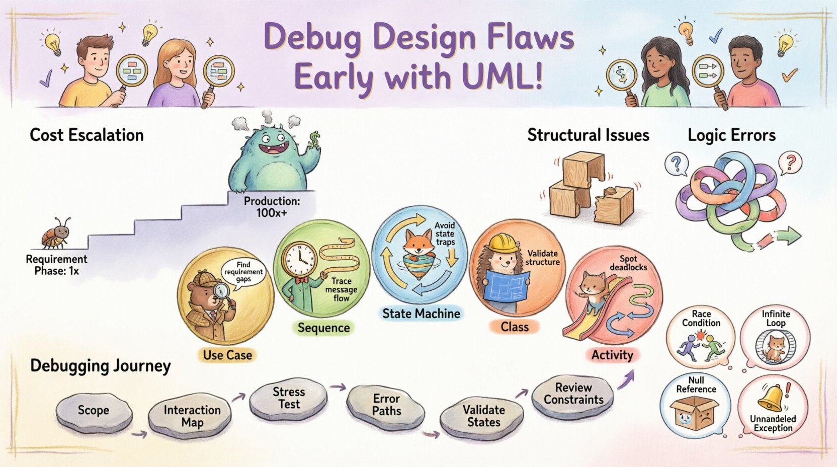
Why Design Flaws Outlast Code Errors 🚫
There is a distinct difference between a syntax error and a design flaw. A syntax error prevents compilation or execution due to grammar violations. A design flaw allows code to run but produces incorrect outcomes under specific conditions. The cost of fixing a design flaw increases significantly as the project progresses.
- Requirement Phase: Fixing a flaw costs 1x.
- Design Phase: Fixing a flaw costs 5x to 10x.
- Coding Phase: Fixing a flaw costs 20x to 50x.
- Production Phase: Fixing a flaw costs 100x or more due to patching and reputation damage.
UML acts as a safety net during the Design Phase. It forces the team to articulate assumptions about data flow, state changes, and object interactions. When these assumptions are visualized, contradictions often become obvious. This process is not about drawing pictures; it is about thinking through scenarios that might break the system.
Understanding Logic Errors vs. Structural Issues 🧠
To debug effectively, one must distinguish between structural problems and logical failures. Structural issues involve how components connect, while logic errors involve how data moves and transforms.
Structural Issues
- Missing dependencies between modules.
- Incorrect relationship cardinality (one-to-many vs. one-to-one).
- Circular dependencies that cause infinite loops during initialization.
- Access control gaps where unauthorized entities can reach protected data.
Logic Errors
- Incorrect state transitions (e.g., an order moving from Shipped to Cancelled without returning).
- Null value handling failures (e.g., a method expecting input but receiving none).
- Boundary condition oversights (e.g., a loop that runs one time too many).
- Concurrency issues where two threads modify the same resource simultaneously.
UML provides specific diagram types to address each category. Using the wrong diagram for the wrong problem leads to wasted effort. The following sections detail which diagrams serve best for debugging specific error types.
Key UML Diagrams for Debugging 📊
Selecting the right view of the system is crucial. Below is a breakdown of the most effective diagrams for identifying early errors.
1. Use Case Diagrams: Requirement Gaps 🔍
Use Case diagrams map actor interactions to system functionality. They are excellent for finding gaps in requirements that lead to logic errors later.
- Debugging Focus: Identify missing actor interactions.
- Common Flaw: An actor exists in the diagram but has no actions associated with them, or vice versa.
- Resolution: Ensure every actor has a defined path to achieve a goal. If a path exists but no diagram, the feature is undocumented.
2. Sequence Diagrams: Flow and Timing ⏱️
Sequence diagrams show object interactions over time. They are the primary tool for finding logic errors related to data flow and timing.
- Debugging Focus: Trace the lifecycle of a message.
- Common Flaw: Messages are sent to objects that do not exist, or return values are ignored.
- Resolution: Check every lifeline. Does the object receiving the message know how to handle it? Is there an error message path if the operation fails?
3. State Machine Diagrams: State Traps 🔄
State diagrams model the behavior of a single object or system component through various conditions. They are critical for preventing logic errors in workflow systems.
- Debugging Focus: Verify all possible states are reachable and exitable.
- Common Flaw: A state has no outgoing transition (a trap state), or two states have conflicting transitions for the same event.
- Resolution: Ensure every state has a defined reaction to external events. Define default transitions for unhandled events.
4. Class Diagrams: Structural Integrity 🏗️
Class diagrams define the static structure of the system. They help identify logic errors rooted in data modeling and inheritance.
- Debugging Focus: Validate relationships and constraints.
- Common Flaw: Inheritance hierarchies that are too deep, making logic hard to trace. Or associations that allow invalid data configurations.
- Resolution: Limit inheritance depth. Verify multiplicities (e.g., ensuring a list cannot contain duplicates if the business logic requires it).
5. Activity Diagrams: Process Logic 📋
Activity diagrams resemble flowcharts. They describe the flow of control from activity to activity. They are ideal for complex business logic.
- Debugging Focus: Branching and merging conditions.
- Common Flaw: Deadlocks where the flow stops because a condition is never met. Or loops that run infinitely.
- Resolution: Add guard conditions to every fork. Ensure every join has a clear termination point.
Comparing Diagram Utility for Error Detection 📋
| Diagram Type | Primary Debugging Target | Error Type Detected | Difficulty to Maintain |
|---|---|---|---|
| Sequence | Interaction Flow | Missing messages, timing issues | Medium |
| State Machine | Object Behavior | Dead states, invalid transitions | High |
| Class | Data Structure | Relationship contradictions, nullability | Low |
| Activity | Business Logic | Deadlocks, infinite loops | Medium |
| Component | Deployment & Integration | Interface mismatches, dependency cycles | Low |
This table highlights that no single diagram solves all problems. A robust debugging strategy involves cross-referencing multiple views.
Step-by-Step Process for UML-Based Debugging 🔧
Integrating UML into the debugging workflow requires discipline. It is not enough to draw diagrams and store them in a repository. The diagrams must be actively used to challenge the design.
Step 1: Define the Scope of the Logic
Identify the specific feature or module you suspect contains logic errors. Is it a payment process? A user authentication flow? Narrowing the scope allows for focused modeling.
Step 2: Create the Interaction Map
Draw a Sequence Diagram for the primary flow. Do not worry about error handling yet. Map the happy path where everything works perfectly.
- List all objects involved.
- Draw arrows for every message passed between objects.
- Ensure every message has a corresponding return value.
Step 3: Stress Test the Happy Path
Walk through the diagram line by line. Ask “What happens if this step takes too long?” or “What if this object is null?” This mental simulation often reveals gaps.
Step 4: Map the Error Paths
Create secondary paths for failure scenarios. If the payment gateway is down, where does the flow go? If the user input is invalid, what is the recovery state?
- Add exception messages to your Sequence Diagram.
- Ensure error handling does not create new deadlocks.
Step 5: Validate State Consistency
Switch to a State Machine Diagram for the core entity involved in the error. Check if the state transitions match the messages in the Sequence Diagram. If the Sequence Diagram shows a “Cancel” message, the State Diagram must have a transition from “Active” to “Cancelled”.
Step 6: Review Structural Constraints
Check the Class Diagram. Do the objects in your Sequence Diagram exist as classes? Are the methods you called actually defined? Are the data types compatible?
Common Scenarios Where UML Catches Errors 💡
Real-world debugging often involves specific patterns of failure. UML exposes these patterns visually.
Scenario 1: The Race Condition
In concurrent systems, two processes might try to update the same data. A Sequence Diagram alone might not show this, but an Activity Diagram with concurrency bars can.
- Visual Cue: Parallel forks in the activity flow.
- Logic Check: Do the parallel paths access the same resource? If so, is there a lock mechanism defined?
- UML Fix: Add synchronization points to the diagram to enforce order.
Scenario 2: The Infinite Loop
A common logic error occurs when a loop condition is never met. An Activity Diagram makes this obvious.
- Visual Cue: A loop structure with no exit condition marked.
- Logic Check: Is there a guarantee that the loop condition will eventually become false?
- UML Fix: Add a guard condition like “[Attempts < Max]” to the loop edge.
Scenario 3: The Null Reference
Code crashes when accessing properties of a null object. A Class Diagram can prevent this.
- Visual Cue: Associations without multiplicity constraints.
- Logic Check: Can the association be empty? If yes, how does the consumer handle it?
- UML Fix: Set multiplicity to “1..1” if the relationship is mandatory, or add a note about nullability checks.
Scenario 4: The Unhandled Exception
Business logic fails silently because an error is caught but not processed.
- Visual Cue: Missing exception messages in Sequence Diagrams.
- Logic Check: Is there a path for the caller to know something went wrong?
- UML Fix: Explicitly draw the exception message returning to the caller. Ensure the caller has a handler defined in the next diagram.
Pitfalls in UML Modeling for Debugging ⚠️
While UML is powerful, misusing it can introduce confusion rather than clarity. Avoid these common traps.
- Over-Modeling: Creating diagrams for every minor detail. This slows down the team and makes maintenance impossible. Focus on high-level logic and complex flows.
- Inconsistent Notation: Using different symbols for the same concept across diagrams. This leads to misinterpretation. Stick to standard UML syntax.
- Outdated Diagrams: Updating code but forgetting to update the model. An outdated model is more dangerous than no model because it gives false confidence.
- Ignoring Constraints: Focusing only on the happy path. Debugging is about finding where things break, so the model must emphasize failure modes.
- Tool Dependency: Relying entirely on automated diagramming tools. Tools can generate structure, but they cannot understand business logic. Manual review is essential.
Maintaining the Model for Long-Term Debugging 🔄
For UML to remain a debugging asset, it must evolve with the system. A static model becomes a liability.
Version Control for Diagrams
Store UML diagrams in the same repository as the source code. This allows you to track changes and see which code modifications correlate with design changes. If a bug appears, check the diagram history to see if the logic changed recently.
Code-Model Synchronization
Implement a process where code generation or reverse engineering keeps the model in sync. If a new method is added to a class, the Class Diagram should reflect it immediately. Automated tools can help here, provided the team verifies the output.
Review Cycles
Include diagram reviews in the standard development cycle. During code reviews, ask the developer to walk through the relevant sequence diagram. This reinforces the link between the design and the implementation.
Advanced Techniques: Combining Views 🔗
Complex systems often require combining multiple UML views to debug deeply.
The Traceability Matrix
Create a mapping between Use Cases, Sequence Diagrams, and Class Diagrams. This ensures that every requirement is implemented and every implementation is traced back to a requirement. Gaps in this matrix often indicate logic errors where code exists without purpose, or requirements exist without code.
Constraint Checking
Use UML Constraints (OCL – Object Constraint Language) to define strict rules. For example, “An Order cannot be Shipped if the PaymentStatus is Pending”. This formalizes logic that might otherwise be implicit. When the model violates the constraint, it is flagged as an error before coding begins.
Simulation and Execution
Some modeling environments allow for the execution of Sequence and Activity diagrams. You can “run” the design to see if it completes. This is effectively white-box testing of the design itself. If the simulation hangs or crashes, the logic is flawed.
Final Considerations for Implementation 🏁
Adopting UML for debugging requires a shift in mindset. It is not a documentation exercise; it is a simulation exercise. The goal is to break the design on paper so it does not break in production.
- Start Small: Pick one critical module and apply this process. Measure the reduction in bugs found in later stages.
- Focus on Logic: Don’t get bogged down in visual aesthetics. A messy diagram that correctly shows a logic error is better than a pretty one that hides it.
- Collaborate: Diagrams are communication tools. Use them in team meetings to discuss edge cases. The collective scrutiny of the group often finds errors one person misses.
- Iterate: Expect to redraw diagrams. As you find flaws, update the model. The updated model becomes the new baseline.
By treating UML as a debugging tool rather than a compliance artifact, teams can significantly reduce the cost of defects. The time invested in modeling early pays dividends in stability and maintainability. Logic errors are often invisible in code until they occur, but in a well-constructed diagram, they stand out as broken paths or missing links. Prioritize clarity and correctness over speed, and let the diagrams guide the code.