
Complexity is the silent killer of system integrity. When a system grows beyond a certain threshold, linear thinking fails. Developers and architects often find themselves lost in a web of interdependent logic, where a change in one module triggers an unforeseen cascade in another. To combat this, we need a structured approach to visualizing behavior. The Unified Modeling Language (UML) offers several tools, but none are as precise for dynamic behavior as the State Machine Diagram. Also known as a State Diagram, this artifact allows us to model the reactive nature of an object or system over time. By breaking down complex systems into manageable states and transitions, we gain clarity where there was once chaos.
Why State Machines Matter for System Decomposition 🛠️
At its core, software is about state management. Every user interaction, every background process, and every data transaction changes the status of the system. A State Machine Diagram provides a formalized way to describe these changes. It answers specific questions that other diagrams cannot:
- What are the distinct modes of operation?
- How does the system react to specific events?
- What conditions must be met before a transition occurs?
- Are there nested behaviors within a single state?
When decomposing a complex system, we are essentially asking how to split a large problem into smaller, solvable sub-problems. State diagrams facilitate this by isolating behavior. Instead of looking at the entire system at once, we focus on the lifecycle of a specific component. This isolation reduces cognitive load. It allows teams to reason about logic without needing to understand the entire codebase immediately. This modularity is crucial for maintenance, testing, and scalability.
Core Elements of a State Diagram 📊
Before diving into decomposition strategies, we must understand the vocabulary. A State Machine Diagram is built from specific symbols. Each symbol carries a distinct meaning regarding the flow of logic. Understanding these elements ensures that the diagram accurately reflects the system’s reality.
| Element | Description | Visual Representation |
|---|---|---|
| State | A condition or situation during the life of an object during which it satisfies some condition, performs some activity, or waits for some event. | Rounded rectangle |
| Transition | A relationship between two states indicating that an object in the first state will move to the second state when a specified event occurs. | Arrow with a label |
| Event | A specification of a signal that causes a transition to occur. | Text label on transition |
| Guard Condition | A Boolean expression that determines whether a transition is enabled. | Text in brackets [ ] |
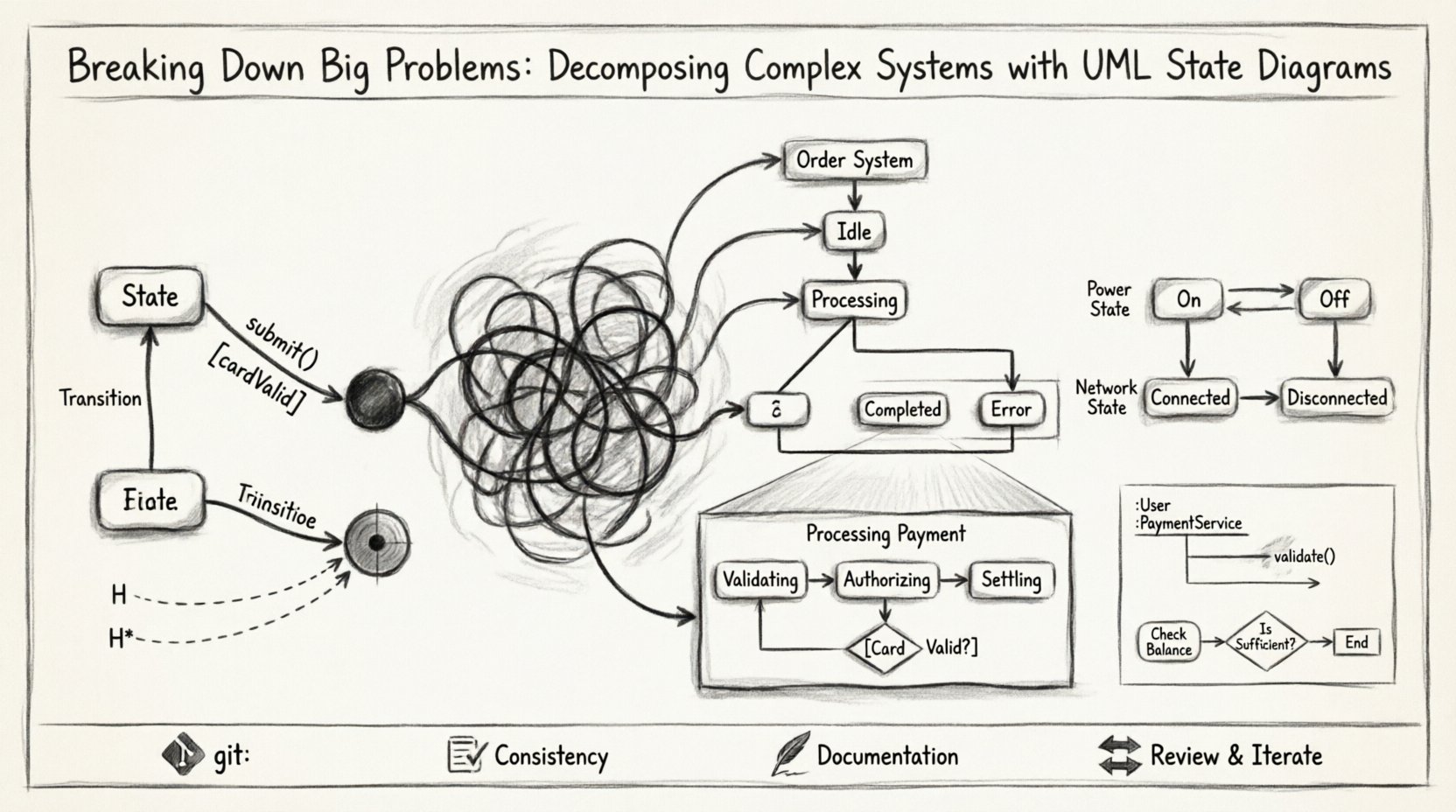
| Initial State | The starting point of the state machine. | Filled black circle |
| Final State | The termination point of the state machine. | Filled black circle within a circle |
Strategies for Decomposing Complexity 🔍
Creating a state diagram for a massive system can be overwhelming if attempted all at once. The key to success lies in decomposition. We do not draw one giant diagram. We break the problem down hierarchically. Here are the primary strategies used to manage this complexity.
1. Vertical Decomposition: Identifying Major States
The first step is to identify the high-level phases of the system. Consider a generic order processing system. You might start with the following major states:
- Idle: The system is waiting for input.
- Processing: The system is actively handling a request.
- Completed: The task has finished successfully.
- Error: Something went wrong and requires intervention.
By isolating these states, we create a skeleton. This skeleton acts as a boundary. When we look at the Processing state, we know it must be broken down further. But we also know we do not need to worry about Idle logic at that moment. This separation of concerns prevents logic from bleeding into unrelated areas.
2. Horizontal Decomposition: Orthogonal Regions
Sometimes a single object has multiple independent behaviors occurring simultaneously. A state machine diagram supports orthogonal regions. This allows us to model concurrency. For example, a smart home device might have a power state and a network state. These two behaviors are independent. The device can be powered on but disconnected from the network, or powered on and connected. Drawing these as separate regions within the same state container clarifies this independence.
- Region A: Manages power cycles (On/Off).
- Region B: Manages connectivity (Connected/Disconnected).
Using orthogonal regions reduces the combinatorial explosion of states. Without this feature, you might need a state for every combination (On+Connected, On+Disconnected, Off+Connected, Off+Disconnected). Orthogonal regions allow you to define the states once and combine them logically.
Nested States and Hierarchy 📉
One of the most powerful features of UML State Machine Diagrams is composite states. This is the mechanism for decomposition. A composite state is a state that contains other states. It acts as a container, allowing us to zoom in on a specific state and define its internal logic without cluttering the parent diagram.
When you encounter a state that is too complex to define with simple transitions, you decompose it. You create a sub-diagram. This sub-diagram is the internal structure of the parent state. This is where the real work of system decomposition happens.
Example: The Payment Process
Consider the Processing Payment state mentioned earlier. This is too complex for a single box. Inside this state, we might have:
- Validating: Checking card details.
- Authorizing: Communicating with the bank.
- Settling: Recording the transaction.
Transitions occur within the Processing Payment state. If validation fails, the system returns to the parent state or moves to an error state. This hierarchy allows us to manage detail. We can view the system at a high level (Order: Processing) or drill down (Payment: Authorizing). This is essential for large teams working on different modules.
Managing Transitions and Guards 🚦
State diagrams are not just about where you are; they are about how you move. Transitions define the movement. However, not all events trigger movement. We need guards. A guard is a condition that must evaluate to true for the transition to occur. This adds logic to the flow without cluttering the visual representation.
For example, consider a login system. The transition from Login Attempt to Authenticated only happens if the password is correct. This is a guard condition.
- Event: Submit Credentials
- Guard: [Password Valid == true]
- Action: Load User Profile
Using guards keeps the diagram clean. It separates the trigger (the event) from the logic (the condition). It also highlights potential failure paths. If the guard is false, the transition does not happen. We must define what happens in that case. Often, this leads to a transition to an Error or Retry state. Explicitly modeling failure paths is a sign of robust system design.
History States and Re-entry 🔄
When a system exits a composite state and later re-enters it, where does it go? This is a critical question for complex systems. If we always return to the initial sub-state, we might lose context. If we return to the last active sub-state, we preserve context. This is the purpose of a History State.
There are two types of history states:
- Deep History (H*): Re-enters the last active state within the composite state, even if nested.
- Shallow History (H): Re-enters the last active state directly within the composite state.
Using history states prevents the system from resetting unnecessarily. For example, if a user is in the middle of a multi-step wizard and the application crashes, they should return to the step they were on, not the beginning. Modeling this with history states ensures the user experience remains consistent with their last known state.
Common Pitfalls in State Modeling 🚫
Even with a powerful tool, errors occur. When decomposing systems, architects often fall into traps that reduce the utility of the diagram.
- Over-Modeling: Creating a state for every single variable change. States should represent significant modes of operation, not every minor data update.
- Missing Transitions: Forgetting what happens when an event occurs but no guard is met. Every event should have a defined outcome.
- Circular Dependencies: Creating states that depend on each other in a way that creates infinite loops. This usually indicates a logical flaw in the system design.
- Ignoring Initial/Final States: A state machine without a clear start or end point is incomplete. It makes testing difficult.
To avoid these issues, review the diagram with a critical eye. Ask if every transition is necessary. Ask if every state adds value. If a state is just a pass-through with no internal logic, it might be redundant.
Integration with Other Diagrams 📐
A State Machine Diagram does not exist in isolation. It works best when integrated with other UML artifacts. For instance, Sequence Diagrams can detail the interactions that trigger the state transitions. If a state changes from Idle to Active, a Sequence Diagram can show the messages exchanged between objects during that moment.
Similarly, Activity Diagrams can describe the internal workflow of a specific state. If the Processing state involves a complex series of calculations, an Activity Diagram can map that flow. The State Diagram provides the high-level control flow, while the Activity Diagram provides the internal logic flow. This combination provides a complete picture of system behavior.
Best Practices for Long-Term Maintenance 🛡️
Once the diagram is created, it becomes a living document. Systems evolve. Requirements change. A static diagram becomes obsolete quickly if not managed. Here are practices to ensure longevity.
- Version Control: Treat diagrams as code. Store them in a version control system. Track changes over time.
- Consistency: Ensure the notation is consistent across the entire project. Do not mix styles.
- Documentation: Add annotations. Explain *why* a transition exists, not just *that* it exists. Context is king.
- Review Cycles: Include diagram reviews in the development lifecycle. When code changes, the diagram must change.
Conclusion on System Clarity 🎯
Decomposing complex systems is not about making things smaller; it is about making them understandable. State Machine Diagrams provide a rigorous framework for this understanding. By isolating behavior into states, managing transitions with guards, and organizing logic through hierarchy, we create a blueprint that developers can follow with confidence.
The complexity of modern software is inevitable. The choice is not whether to model it, but how to model it effectively. State diagrams offer a path through the noise. They transform abstract logic into visual structure. They turn potential errors into defined transitions. They turn chaos into order.
When you sit down to design a new system, do not start with the code. Start with the states. Define where the system can be. Define how it moves. Define what happens when things go wrong. This approach builds resilience into the architecture from the ground up. It ensures that when the system grows, the logic remains clear. This is the foundation of reliable engineering.