
Creating a clear visual representation of system functionality is a critical skill for any software architect or business analyst. A UML Use Case Diagram serves as a bridge between technical implementation and business needs. However, when these diagrams become cluttered or ambiguous, they lose their value entirely. This guide provides a structured approach to constructing diagrams that communicate effectively without requiring years of experience.
Why Readability Matters in System Design 🧠
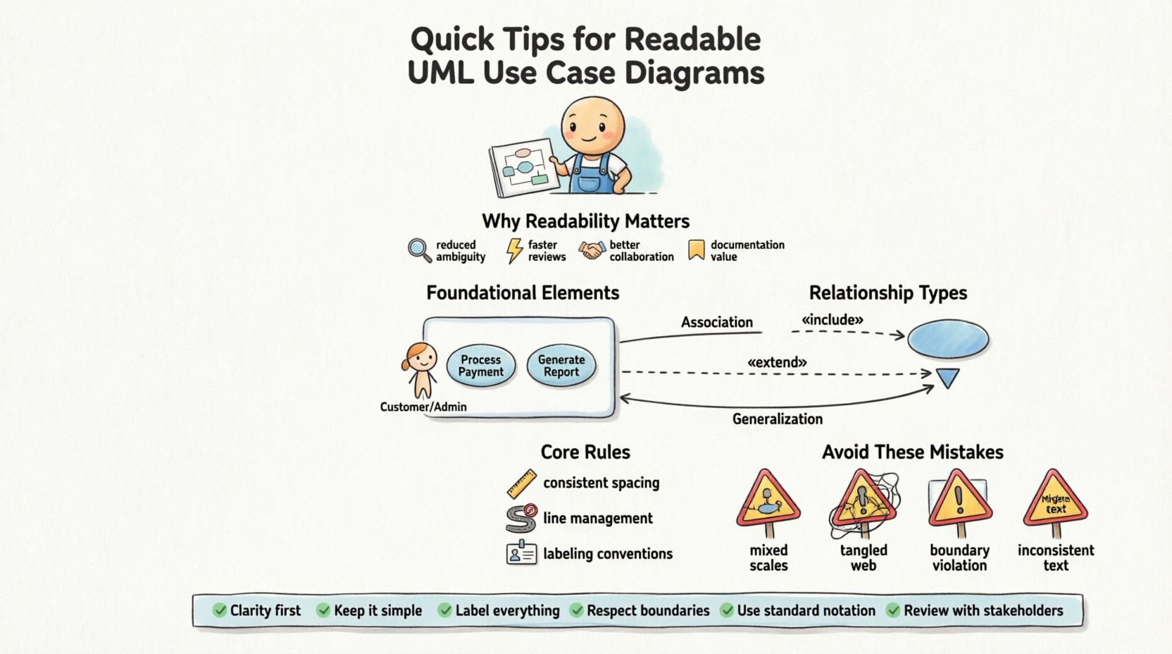
A diagram is not merely a drawing; it is a communication tool. If stakeholders cannot understand the diagram within minutes, the design process has failed. Readability reduces cognitive load. When a diagram is clean, stakeholders focus on the logic rather than deciphering the notation. Clarity prevents misinterpretation of requirements, which saves significant time during development and testing phases.
Consider the following benefits of a well-structured diagram:
- Reduced Ambiguity: Clear lines and labels leave no room for guessing.
- Faster Review Cycles: Stakeholders can validate functionality quickly.
- Better Collaboration: Developers and testers share a single source of truth.
- Documentation Value: The diagram serves as a lasting reference for future maintenance.
Foundational Elements of a Use Case Diagram 🏗️
Before drawing lines, you must understand the building blocks. Each element carries specific semantic meaning. Misusing these elements leads to confusion. The core components include Actors, Use Cases, and Relationships.
1. Actors: Who Interacts with the System? 👤
An actor represents a role rather than a specific person. A “Customer” actor remains valid whether it is John or Jane. Actors exist outside the system boundary. They initiate actions or receive information.
- Primary Actors: Those who initiate the use case to achieve a goal.
- Secondary Actors: Systems or services that the main system interacts with.
- Generalized Actors: Sub-classes of actors that share common traits.
Tip: Do not draw specific user names. Stick to roles like “Admin”, “Guest”, or “Payment Gateway”.
2. Use Cases: What Does the System Do? ⚙️
Use cases represent functional requirements. They are described as actions the system performs. Each use case should answer the question: “What is the system doing for the actor?”
- Verb-Noun Format: Name use cases like “Process Payment” or “Generate Report”.
- Atomic Goals: Each oval should represent a single, complete goal.
- System Boundary: Use cases exist inside the rectangle representing the system.
3. System Boundary: Defining Scope 🚧
The system boundary is a rectangle enclosing all use cases. Everything inside is part of the system. Everything outside is external. This visual distinction is crucial for understanding scope.
- Clear Edges: Ensure the box is visible and not obscured by other elements.
- Labeling: Place the system name clearly at the top of the boundary.
Pre-Drawing Preparation: Planning Your Layout 📝
Starting immediately with the drawing tool often leads to messy results. A brief planning phase ensures spatial efficiency and logical grouping.
1. Define the Scope First 🎯
List all potential actors and use cases on paper or a whiteboard before moving to the digital canvas. This prevents the common issue of running out of space on the diagram later. Ask yourself what is essential for Version 1.0 and what can be deferred.
2. Group Related Functionality 📦
Use packages or logical groupings to organize use cases. If a system has “Reporting” features and “User Management” features, group them visually. This allows readers to scan for specific domains quickly.
3. Determine Actor Placement 📍
Place actors where they interact most frequently. If a specific actor interacts with ten different use cases, place them centrally. Peripheral actors can sit at the edges. This reduces the length of connecting lines.
Core Drawing Rules for Clarity ✍️
Once planning is complete, follow these rules to maintain visual consistency and professional standards.
1. Consistent Spacing and Alignment 📏
Irregular spacing creates visual noise. Use a grid or alignment guides to ensure actors and use cases are evenly distributed. Overlapping elements should be avoided unless absolutely necessary.
- Horizontal Alignment: Align actors in a row if they interact with the system similarly.
- Vertical Alignment: Align use cases if they represent a workflow sequence.
2. Line Management and Crossing 🚦
Line crossings are the enemy of readability. When lines cross, the eye gets confused about which line belongs to which actor. Try to route lines around other elements. If a crossing is unavoidable, ensure it does not happen near the actors or use cases themselves.
3. Labeling Conventions 🏷️
Labels must be concise. Avoid long sentences inside use case ovals. Use standard capitalization (Title Case) for consistency.
- Actor Labels: Upper Case or CamelCase (e.g., System Administrator).
- Use Case Labels: Verb + Noun (e.g., Update Profile).
- Relationship Labels: Add text only when necessary to clarify direction or type.
Understanding Relationships: The Connectors 🔗
The connections between actors and use cases define the flow of information. There are four primary relationship types. Understanding the nuance between them is vital for accuracy.
Association: Direct Interaction 🔗
This is the standard line connecting an actor to a use case. It indicates that the actor initiates or participates in the use case.
- Solid Line: Represents a standard association.
- Arrowheads: Indicate direction of information flow or initiation.
Include: Mandatory Behavior ➕
An include relationship means one use case requires another use case to complete. It is mandatory. If the included use case fails, the main use case cannot succeed.
- Use Case: Main flow.
- Include: Shared sub-flow (e.g., “Login” included in “Checkout”).
Extend: Optional Behavior ➡️
An extend relationship means one use case adds behavior to another under specific conditions. It is optional. If the condition is not met, the extension does not happen.
- Base Use Case: The primary flow.
- Extension: Conditional behavior (e.g., “Apply Discount” extends “Checkout”).
Generalization: Inheritance 🔄
This relationship indicates that a specific actor or use case is a specialized version of a general one. It reduces redundancy by allowing shared behaviors to be defined once.
| Relationship | Meaning | Visual Style | Example |
|---|---|---|---|
| Association | Actor uses Use Case | Solid Line | User clicks “Search” |
| Include | Mandatory sub-step | Dashed Line + «include» | Login required to Checkout |
| Extend | Optional sub-step | Dashed Line + «extend» | Apply Promo Code |
| Generalization | Inheritance | Solid Line + Hollow Triangle | Admin is a User |
Common Mistakes to Avoid 🛑
Even experienced practitioners make errors. Recognizing these pitfalls helps you maintain high standards from the start.
1. Mixing Levels of Abstraction 📉
Do not mix high-level goals with low-level tasks. “Manage System” is too vague. “Update System Settings” is better. “Click Save Button” is too detailed for a use case diagram. Keep the granularity consistent.
2. Overusing Relationships 🕸️
Every relationship adds complexity. Do not use include or extend for every step. If a flow is linear, an association is sufficient. Reserve complex relationships for shared or conditional logic.
3. Ignoring the Boundary 🧱
Placing use cases outside the system boundary implies they are external. Placing actors inside implies they are part of the system logic. Keep the boundary strict. Actors must always be outside.
4. Inconsistent Naming 📝
Using “Buy Item” in one place and “Purchase Product” in another confuses readers. Establish a naming convention at the beginning of the project and stick to it.
Validation: Checking Your Work ✅
Before finalizing the diagram, perform a validation check. This ensures the diagram is accurate and usable.
- Traceability: Can you trace every actor to a use case they need?
- Completeness: Are all actors and use cases accounted for?
- Readability: Can a new stakeholder understand the diagram in 5 minutes?
- Consistency: Are all lines straight and angles 90 degrees?
Maintaining the Diagram Over Time 🔧
Software evolves. Requirements change. A diagram drawn today may be obsolete tomorrow. Treat the diagram as a living document.
1. Version Control 📂
Keep track of changes. If a use case is removed or added, note the version. This helps in auditing and understanding the history of requirements.
2. Regular Reviews 🗓️
Review the diagram during sprint planning or requirement gathering. Ensure it reflects the current state of the system. Update labels if business terminology changes.
3. Link to Requirements 📋
Link use cases to detailed requirement documents. This allows stakeholders to drill down from the visual diagram to the text specification when needed.
Advanced Tips for Complex Systems 🚀
For larger systems, a single diagram may become too crowded. Here is how to handle scale.
1. Use Packages 📁
Group related use cases into packages. You can then create a summary diagram showing the packages and a detailed diagram for each package. This reduces clutter on the main view.
2. Focus on Key Actors 🎯
If there are many actors, focus on the primary ones in the main diagram. Secondary actors can be documented in text or separate diagrams if they do not drive the main functionality.
3. Leverage White Space 🌬️
Do not fear empty space. It helps the eye rest. Crowded diagrams suggest complexity and confusion. Allow breathing room between elements.
Conclusion on Best Practices 🌟
Building a readable UML Use Case Diagram is about discipline and clarity. By following these steps, you ensure that your diagrams serve their purpose as effective communication tools. Remember to plan before drawing, maintain consistent naming, and validate your work regularly. A well-constructed diagram pays dividends throughout the development lifecycle by preventing misunderstandings and aligning the team.
Focus on the value the diagram provides to the team. If it aids understanding, it is a success. If it creates confusion, it is a failure. Keep the goal simple: clarity.
Summary Checklist 📋
- Define actors as roles, not people.
- Name use cases with Verb + Noun.
- Keep actors outside the system boundary.
- Use include for mandatory steps.
- Use extend for optional steps.
- Avoid line crossings where possible.
- Review for consistency and completeness.
- Update the diagram as requirements change.