
Systems analysis serves as the bridge between business requirements and technical implementation. At the heart of this translation process lies the Unified Modeling Language (UML), and specifically, the Use Case Diagram. This visual representation defines the interactions between users (actors) and the system itself. However, a diagram is only as good as the logic underpinning it. An inaccurate diagram leads to scope creep, missed requirements, and costly development errors.
Before moving to the detailed design or coding phases, a Systems Analyst must validate the structural integrity of the model. This guide outlines the critical steps required to ensure your Use Case Diagram is robust, complete, and aligned with business goals. We will explore the preparation phase, the core elements, relationships, boundaries, and validation techniques.
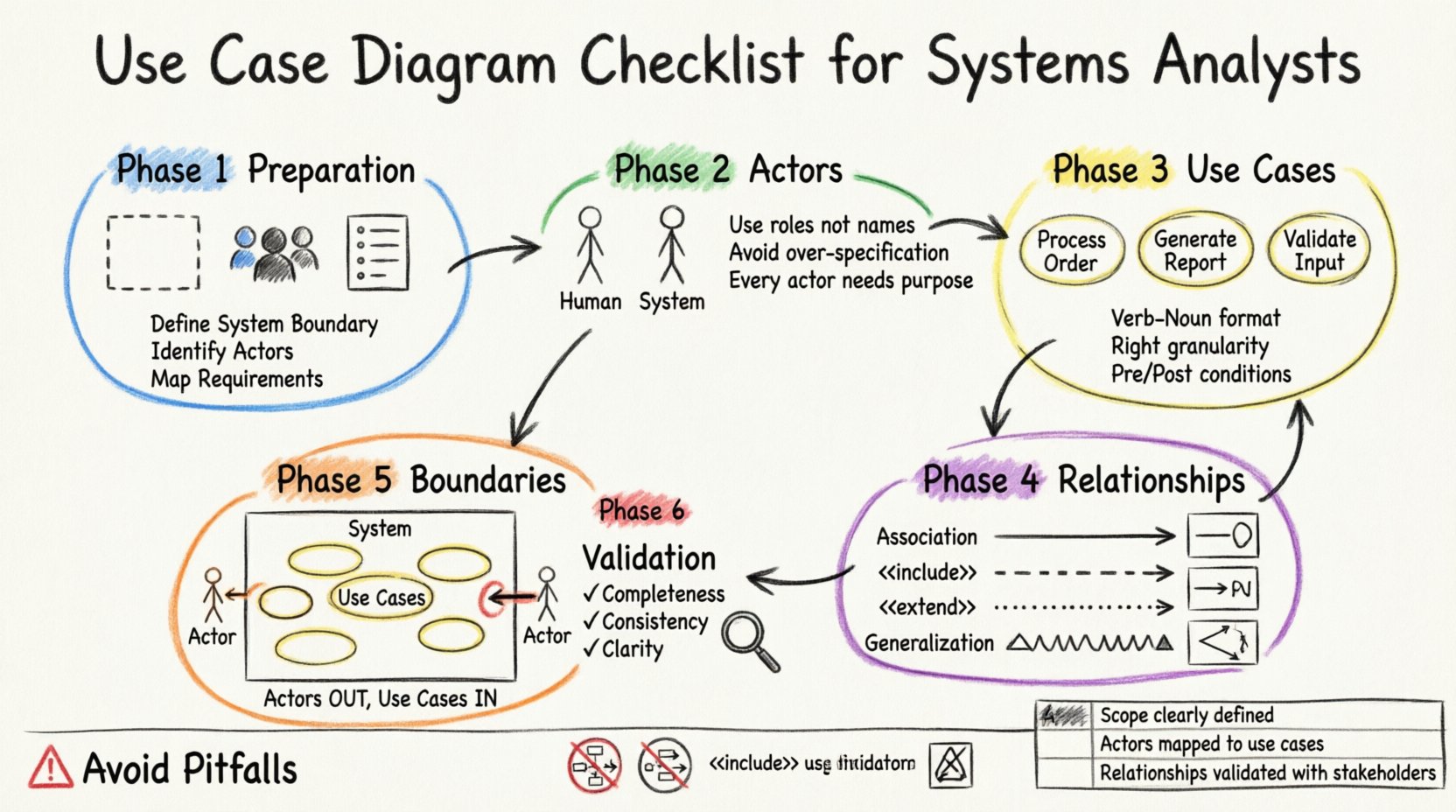
🛠️ Phase 1: Preparation and Context
Before drawing a single circle or line, the foundation must be solid. A Use Case Diagram is not created in a vacuum; it relies on the clarity of the problem statement and the understanding of the users involved.
1. Define the System Scope
Clarity regarding what is inside the system and what is outside is paramount. Ambiguity here leads to confusion about responsibility. Ask the following questions during the scoping phase:
- What specific functionality is included within this iteration of the project?
- Are there external systems that this model must acknowledge but not control?
- Does the system handle data storage, or is it purely a processing layer?
Clearly marking the system boundary prevents stakeholders from expecting features that fall outside the agreed-upon scope. It also helps in identifying dependencies that might affect performance or security.
2. Identify Stakeholders
Stakeholders are individuals or groups with an interest in the system’s outcome. They are not necessarily the direct users, but their needs drive the requirements.
- Primary Stakeholders: Those who directly benefit from the system (e.g., customers, operators).
- Secondary Stakeholders: Those who support the system but do not interact with it directly (e.g., maintenance staff, regulators).
Ensuring all key voices are represented early prevents the need to redraw the diagram later when a critical requirement is uncovered.
3. Gather Functional Requirements
The diagram must reflect the functional requirements document. Cross-reference every potential use case against the requirement list. If a requirement exists without a corresponding use case, it is missing. If a use case exists without a requirement, it may be scope creep.
👥 Phase 2: Actor Identification and Classification
Actors represent the roles played by people, external systems, or devices that interact with the subject system. They are the external entities initiating or participating in the use cases.
1. Distinguish Human vs. Non-Human Actors
Do not limit actors to humans. A sensor, a legacy database, or an automated billing service can all be actors.
- Human Actors: Represented by stick figures. Use specific roles (e.g., Administrator, Cashier) rather than specific names (e.g., John).
- External Systems: Represented by stick figures or icons. Label them clearly to indicate they are technical interfaces.
2. Avoid Over-Specification
A common error is creating too many actor types. If two users perform the exact same actions, group them under a single role. For example, instead of creating Manager and Director as separate actors, combine them into Executive if their system interactions are identical. This keeps the diagram clean and maintainable.
3. Check Actor Responsibility
Ensure every actor has a clear purpose. An actor should not be included merely to “make the diagram look balanced.” If an actor does not trigger a use case or receive a result, remove them. Every line drawn should signify a data or control flow.
🎯 Phase 3: Use Case Definition
Use cases are the specific goals or tasks that actors perform within the system. They are the core building blocks of the diagram.
1. Naming Conventions
Names must be consistent and descriptive. Use a Verb-Noun structure to clearly state the action.
- Correct: “Process Order”, “Generate Report”, “Update Profile”.
- Incorrect: “Order”, “Report”, “User”.
Clear naming ensures that developers and business stakeholders interpret the functionality in the same way.
2. Granularity Level
Decide on the level of detail. A use case should not be too broad (e.g., “Manage System”) nor too narrow (e.g., “Click Save Button”).
- Too Broad: “Manage System” implies too many steps and variations. It should be broken down into “Manage User”, “Manage Settings”, etc.
- Too Narrow: “Click Save Button” is an interface interaction, not a system goal. The goal is “Save Data”.
3. Preconditions and Postconditions
While often detailed in the Use Case Specification document, the diagram should reflect logical boundaries.
- Preconditions: What must be true before the use case starts? (e.g., User must be logged in).
- Postconditions: What is true after the use case finishes? (e.g., Order status is confirmed).
If a precondition is not met, the system should not proceed. This logic must be understood by the analyst before finalizing the diagram.
🔗 Phase 4: Relationship Mapping
Relationships define how actors and use cases interact. Misinterpreting these lines is the most common source of modeling errors.
1. Association
Association is the standard link between an actor and a use case. It indicates that the actor initiates or participates in the use case.
- Ensure lines are not crossed unnecessarily. If a line crosses another, consider using an inclusion point or repositioning.
- Verify directionality. While UML associations are generally bidirectional, the flow of control usually goes from Actor to Use Case.
2. Include Relationship
An ✾ < relationship means one use case incorporates another. The included use case is mandatory. It is used to factor out common behavior.
- Example: “Place Order” includes “Log In”. You cannot place an order without logging in.
- Check: Does the base use case make sense without the included one? If not, the relationship is likely correct. If the base use case is incomplete without it, it is a strong candidate for inclusion.
3. Extend Relationship
An ✾ < relationship means one use case adds functionality to another under specific conditions. It is optional.
- Example: “Place Order” is extended by “Apply Coupon”. The coupon step only happens if the user chooses to apply one.
- Check: Does the extending use case require the base use case to be active? Yes. The base use case must be able to stand alone.
4. Generalization (Inheritance)
Generalization represents a “is-a” relationship between actors or between use cases.
- Actor Inheritance: A “VIP Customer” is a type of “Customer”. The VIP customer inherits the abilities of a standard customer and adds specific ones.
- Use Case Inheritance: A specific use case inherits behavior from a more general one. Use this sparingly to avoid deep hierarchies that confuse readers.
🧱 Phase 5: System Boundary and Context
The system boundary is the box that encloses the use cases. Everything outside is the environment; everything inside is the system.
1. Crossing Boundaries
Actors must always exist outside the system boundary. Use cases must always exist inside. An actor inside the box implies the actor is part of the system’s internal logic, which is incorrect.
2. External Interfaces
If the system communicates with another software system, represent that system as an external actor. Do not draw internal use cases that represent “Sending Data to API”. Instead, draw a use case “Send Data” and link it to the External System Actor.
✅ Phase 6: Validation and Review
Before signing off, the diagram must undergo a rigorous review process. This section ensures consistency, completeness, and clarity.
1. Completeness Check
Review the diagram against the requirements document. Is every requirement represented? Is every actor identified? Are all necessary relationships defined?
2. Consistency Check
Ensure naming conventions are consistent throughout. Check for duplicate use cases that might have slightly different names (e.g., “Login” vs “Log In”). Check for orphaned actors or use cases with no connections.
3. Ambiguity Reduction
Look for lines that cross without explanation. Complex diagrams can become unreadable. If a diagram has more than 10-15 use cases, consider splitting it into subsystems or packages to improve readability.
📊 Comprehensive Review Checklist
Use the following table as a quick reference tool before finalizing your work.
| Category | Item to Verify | Pass/Fail |
|---|---|---|
| Scope | System boundary clearly defined? | ✓ |
| Actors | Are actors outside the boundary? | ✓ |
| Actors | Are roles named generically (not specific people)? | ✓ |
| Use Cases | Are names in Verb-Noun format? | ✓ |
| Use Cases | Are use cases inside the boundary? | ✓ |
| Associations | Does every actor connect to at least one use case? | ✓ |
| Relationships | Are Include/Extend relationships used correctly? | ✓ |
| Logic | Are there circular dependencies? | ✓ |
| Documentation | Are prerequisites defined for complex flows? | ✓ |
🚫 Common Pitfalls to Avoid
Even experienced analysts can fall into traps. Being aware of common mistakes helps maintain high standards.
1. The “Flowchart” Mistake
A Use Case Diagram is not a flowchart. It does not show the step-by-step sequence of events within a use case. That belongs in the Use Case Description or Activity Diagram. Do not add decision diamonds or process arrows to the diagram.
2. Data Flow Confusion
Do not try to show data passing through the system on the diagram. The diagram shows interaction, not data structure. If you need to show data, use a Class Diagram or Data Dictionary.
3. Overuse of Include
Using ✾ < for every small step makes the diagram fragmented. Only use it for truly common, reusable functionality that is invoked by multiple other use cases.
4. Ignoring Non-Functional Requirements
While Use Case Diagrams focus on function, they should not ignore constraints. If a specific use case has a heavy security requirement or a performance constraint, note this in the accompanying documentation. The diagram itself remains focused on interaction.
🔍 Detailed Relationship Analysis
To ensure the highest quality, let us dig deeper into the relationships, as this is where most confusion arises.
Understanding <> vs. <>
The distinction is often subtle but critical for developers.
- Include is Mandatory: If Use Case A includes Use Case B, you cannot execute A without B. It is a dependency. Think of it as a subroutine call.
Example: “Withdraw Cash” includes “Verify PIN”. - Extend is Optional: If Use Case B extends Use Case A, the extension happens only if a specific condition is met. It adds optional behavior.
Example: “Withdraw Cash” is extended by “Request Overdraft”. You only request overdraft if you don’t have enough funds.
When reviewing your diagram, ask: “Can the base use case function without the extended one?” If yes, it is an extension. If no, it is likely an include.
Actor Inheritance Logic
When defining actor hierarchies, ensure the child actor inherits all permissions of the parent. If a “Manager” inherits from “Employee”, the Manager should be able to perform all Employee actions plus Manager-specific actions. Do not remove parent capabilities unless explicitly stated as a restriction.
📝 Finalizing the Documentation
Once the diagram is visually complete and logically sound, the documentation phase begins. The diagram is a summary; the text provides the depth.
1. Add Annotations
If a relationship is complex or a use case has specific constraints, use notes or annotations to clarify. Keep these concise. Do not clutter the diagram with paragraphs of text.
2. Version Control
Ensure the diagram is versioned. As requirements change, the diagram must evolve. Keep a log of what changed in each iteration. This helps in tracking scope creep and understanding why certain elements were added or removed.
3. Stakeholder Sign-Off
Before handing the diagram to the development team, have the business stakeholders review it. They need to confirm that the diagram accurately reflects their needs. Do not assume the technical team understands the business intent without validation.
🔗 Integrating with Other Models
The Use Case Diagram does not exist alone. It is part of a larger modeling ecosystem.
1. Connection to Class Diagrams
The actors and use cases defined here should inform the classes and objects in the Class Diagram. Ensure that the nouns identified in the Use Case descriptions align with the nouns in the Class Diagram.
2. Connection to Sequence Diagrams
For complex use cases, a Sequence Diagram provides the timeline of interactions. The Use Case Diagram identifies what happens; the Sequence Diagram identifies how it happens in time.
🛡️ Security Considerations
Security is often overlooked in the early modeling phases. However, access control is intrinsic to actor roles.
1. Role-Based Access
Ensure that sensitive use cases (e.g., “Delete Record”, “Approve Loan”) are only accessible by appropriate actor roles. If a “Guest” actor can access an “Admin” use case, the diagram highlights a critical security flaw.
2. Authentication Flows
Ensure that “Login” or “Authenticate” use cases are included in the flow for any protected area. Do not assume the system handles security automatically without explicit modeling.
🧩 Handling Complex Scenarios
Sometimes, requirements are too complex for a single diagram.
1. Subsystems
If the system is large, divide it into subsystems. Create a high-level diagram showing major subsystems as actors, and detailed diagrams for each subsystem. This keeps the main view clean.
2. Package Diagrams
Use packages to group related use cases. For example, a “Billing Package” and a “Reporting Package”. This helps in organizing the diagram without losing the actor relationships.
🚀 Moving Forward
With the checklist complete, the diagram is ready for the next stage of development. This artifact will serve as the contract between business and technology. It ensures that everyone understands the system’s capabilities and limitations.
Key Takeaways
- Clarity is King: A diagram should be understandable by non-technical stakeholders.
- Consistency Matters: Maintain naming conventions and structural rules.
- Validation is Crucial: Review against requirements before finalizing.
- Iterate: Models evolve as understanding deepens.
By adhering to this checklist, Systems Analysts can produce high-quality Use Case Diagrams that facilitate clear communication and successful project delivery. The effort invested in this phase pays dividends in reduced rework and higher stakeholder satisfaction.
Remember, the goal is not just to draw a diagram, but to model the system accurately. Treat the diagram as a living document that reflects the truth of the business requirements.