
State Machine Diagrams serve as the backbone for modeling dynamic behavior within complex systems. They provide a visual representation of how a system responds to events over time. However, the complexity of real-world logic often leads to subtle errors that can cause significant issues during implementation. A diagram that looks correct visually might fail under specific edge cases. This guide outlines a rigorous process for validating UML State Diagrams to ensure logical integrity and operational reliability.
🔍 Why Validation Matters in System Design
Before writing a single line of code, the state diagram must be scrutinized. Errors found late in the development cycle are expensive to fix. A state machine defines the lifecycle of an object or system. If the transitions are flawed, the system may enter dead states, loop infinitely, or ignore critical events. Validation is not a final step; it is an iterative process woven into the design phase.
Effective validation ensures that:
- All possible events are accounted for.
- The system reaches a valid termination point.
- There are no unreachable states.
- Guard conditions accurately reflect business rules.
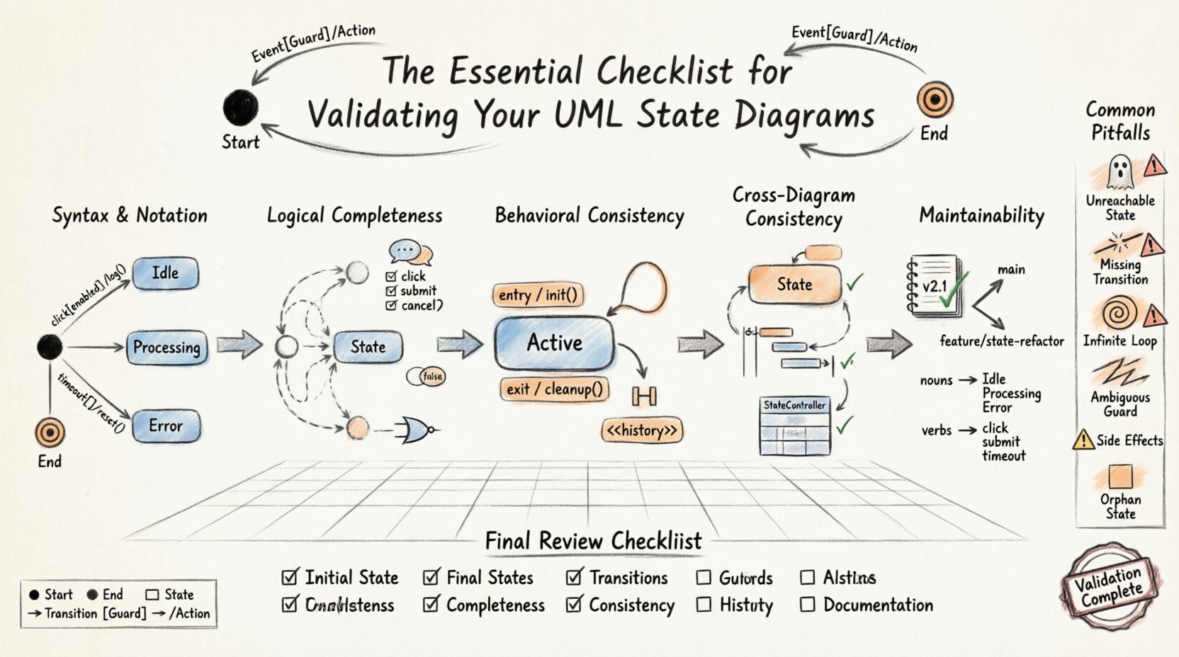
🛠 Phase 1: Syntax and Notation Accuracy
The foundation of any state diagram is correct notation. UML provides a standardized set of symbols. Deviations can lead to misinterpretation by developers and stakeholders. This phase focuses on the structural correctness of the diagram elements.
1.1 Start and End States
Every valid state machine must have a clear entry point and exit points. The initial state is represented by a solid black circle. The final state is represented by a solid black circle within a larger circle. Ensure these exist and are unique.
- Is there exactly one initial state?
- Are all final states clearly marked?
- Do all paths lead to a final state or a stable waiting state?
1.2 State Representation
States are depicted as rounded rectangles. Each state should represent a distinct condition of the system. Avoid vague labels. A state named “Processing” is less useful than “Processing Order”. Ensure the labels are consistent with the system glossary.
1.3 Transition Labels
Transitions connect states. They are labeled with the triggering event. Optional guard conditions appear in square brackets. Optional actions appear after a forward slash. Verify the syntax:
- Event[Guard]/Action
- Event[Guard]
- Event/Action
Check that brackets are properly closed and slashes are in the correct position. Ambiguous syntax leads to ambiguous logic.
🧠 Phase 2: Logical Completeness
Syntax is not enough. The logic must hold up under scrutiny. This phase involves walking through the diagram to ensure every scenario is handled.
2.1 Reachability Analysis
Every state must be reachable from the initial state. If a state cannot be entered from the start, it is dead code. Conversely, ensure there are no states from which the system cannot exit (unless it is a final state). This is often called a “Deadlock” check.
2.2 Event Coverage
For every state, consider every possible event. Does the state handle all incoming events? If an event occurs that has no defined transition, the system behavior is undefined. You must decide if the system ignores the event or moves to an error state. Document this decision explicitly.
2.3 Guard Condition Verification
Guard conditions determine if a transition is allowed. They must be boolean expressions that are always true or false. Avoid side effects within guard conditions. The condition should only evaluate data, not trigger actions. Check that guard conditions cover all logical possibilities. For example, if a transition requires age > 18, ensure there is a path for age <= 18.
⚙️ Phase 3: Behavioral Consistency
Once the structure is sound, focus on the behavior. How does the system react? This phase examines the internal logic of states and transitions.
3.1 Entry and Exit Actions
States can have entry and exit actions. An entry action runs when entering the state. An exit action runs when leaving the state. Ensure these actions do not conflict. For example, an exit action from State A should not depend on a condition that State B fails to meet upon entry.
3.2 Internal Transitions
Internal transitions allow an event to occur without changing the state. This is useful for handling events that modify state data without altering the state itself. Ensure these are used correctly. Do not confuse internal transitions with self-loops. A self-loop implies a transition out and back in. An internal transition implies staying in place.
3.3 History States
When a composite state is re-entered, should the system return to the initial sub-state or the previously active sub-state? Use Shallow History (H) for the last active sub-state. Use Deep History (<<history/>>) for the last active state within nested structures. Validate that the history mechanism matches the user expectation. If a user expects to pick up where they left off, ensure the history state is configured correctly.
📊 Common Pitfalls and Validation Table
Reviewing common errors helps prevent them during the design process. The following table summarizes frequent issues found during validation.
| Pitfall | Impact | Validation Check |
|---|---|---|
| Unreachable State | Code is written but never executed | Trace path from Initial State to the target state |
| Missing Transition | System hangs or errors on specific input | List all events and verify a transition exists for each |
| Infinite Loop | System becomes unresponsive | Check for cycles without guard conditions or exit conditions |
| Ambiguous Guard | Multiple transitions trigger simultaneously | Ensure guard conditions are mutually exclusive |
| Side Effects in Guards | Logic is hard to test and debug | Ensure guards contain only boolean checks |
| Orphan State | No incoming or outgoing transitions | Verify every state has at least one incoming and one outgoing link |
🔄 Phase 4: Consistency Across Diagrams
State diagrams rarely exist in isolation. They are part of a larger model. Consistency across multiple diagrams is crucial for maintaining a coherent system view.
4.1 Interaction with Sequence Diagrams
Verify that events in the state diagram match the messages exchanged in Sequence Diagrams. If a state diagram expects a “PaymentApproved” event, the sequence diagram must show this message being sent by the payment service. Mismatches here indicate a gap in requirements.
4.2 Class Diagram Alignment
Ensure the attributes referenced in guard conditions exist in the Class Diagram. If a state transition depends on “balance > 0”, the Account class must have a “balance” attribute. This alignment prevents runtime errors where variables are undefined.
4.3 Activity Diagram Coordination
Activity diagrams show workflows. State diagrams show object lifecycles. Ensure that the workflow steps align with state changes. For example, an activity “Validate User” should correspond to a transition into a “Validated” state.
🛡 Phase 5: Maintainability and Documentation
A state diagram is a living document. It will evolve as requirements change. Validation includes ensuring the diagram is easy to maintain.
5.1 Naming Conventions
Adopt strict naming conventions. Use nouns for states and verbs for events. This makes the diagram readable to new team members. Avoid abbreviations unless they are industry standard.
5.2 Grouping and Nesting
Use composite states to group related sub-states. This reduces visual clutter. However, do not nest too deeply. Deep nesting makes validation difficult. Limit nesting to two or three levels. Use orthogonal regions if a state can exist in multiple conditions simultaneously.
5.3 Version Control
Treat diagrams as code. Track changes in a version control system. Ensure that diagrams are versioned alongside the code they model. This allows you to revert to previous states if a new design introduces bugs.
🧩 Advanced Scenarios
Complex systems often require advanced features. Validate these with extra care.
6.1 Concurrent Regions
When a state has multiple orthogonal regions, it represents concurrency. Ensure that the events in one region do not inadvertently trigger transitions in another unless explicitly designed. This is a common source of race conditions in implementation.
6.2 Exception Handling
Define explicit paths for exceptions. Every state should have a mechanism to handle unexpected errors. This often involves a generic “Error” state or a specific “Retry” state. Do not rely on the system to crash and restart as a valid state transition.
6.3 Timing Constraints
Some transitions depend on time. A timer event might trigger a transition after 5 seconds. Validate that the timer logic is feasible within the system architecture. Ensure that timers are reset when entering states that require them.
🔎 Final Review Steps
Before finalizing the diagram, perform a final review using the following checklist items.
- ✅ Initial State: Is there one unique start point?
- ✅ Final States: Are all paths capable of terminating?
- ✅ Transitions: Are all transitions labeled with events?
- ✅ Guards: Are all guard conditions valid and exclusive?
- ✅ Actions: Are entry/exit actions defined where needed?
- ✅ Completeness: Are all states reachable and exit-able?
- ✅ Consistency: Do labels match Class and Sequence diagrams?
- ✅ Clarity: Is the diagram readable without excessive zooming?
- ✅ History: Are history states used correctly if nested?
- ✅ Documentation: Is there a legend or key for symbols?
🚀 Implementation Considerations
Once the diagram is validated, the focus shifts to implementation. The diagram serves as the specification. Developers should use the diagram to write state machine code. Ensure that the implementation matches the diagram exactly. If the implementation diverges, update the diagram. This synchronization is critical for long-term system health.
Testing should be driven by the state diagram. Write test cases for every state and every transition. This is known as state coverage testing. It ensures that the logic behaves as modeled. Automated testing frameworks can often be configured to traverse state machines directly, reducing manual effort.
🔗 Integrating with Agile Processes
In agile environments, diagrams evolve rapidly. Validation must be part of the sprint cycle. Do not wait for a “big design up front” session. Validate diagrams continuously as user stories are refined. This ensures that the model remains accurate throughout the development lifecycle.
When a feature is added, update the state diagram first. Then, validate it. Then, implement the code. This order prevents the code from becoming the source of truth while the diagram becomes outdated. The diagram should always lead the way.
📝 Summary of Best Practices
Validating UML State Diagrams requires attention to detail and a systematic approach. It is not enough to draw the boxes and lines correctly. The logic within must be robust. By following the phases outlined above, teams can reduce errors and improve system reliability. Focus on syntax, logic, behavior, consistency, and maintainability. Use tables to track common pitfalls. Use checklists to ensure nothing is missed.
Remember that a state diagram is a communication tool. It must be understood by developers, testers, and stakeholders. Clarity is as important as correctness. If a diagram is confusing, it will be misunderstood, regardless of its logical accuracy. Invest time in making the diagram clean and readable.
Adopting a rigorous validation process pays off in reduced debugging time and higher quality software. Treat the state diagram as a critical artifact. It defines how the system behaves under stress. Ensure it is built to last.