
The landscape of software architecture is constantly shifting. As organizations adopt distributed systems, microservices, and cloud-native infrastructure, the tools used to model these systems must adapt. Among the foundational tools for system design, the UML Use Case Diagram remains a staple for visualizing functional requirements. However, the methods by which these diagrams are created, maintained, and utilized are undergoing a significant transformation.
This guide explores the trajectory of the UML Use Case Diagram. We examine how it fits into modern workflows, the impact of automation and artificial intelligence, and the shifting balance between documentation and execution. The goal is to provide a clear understanding of the future state of system modeling without relying on buzzwords or obsolete practices.
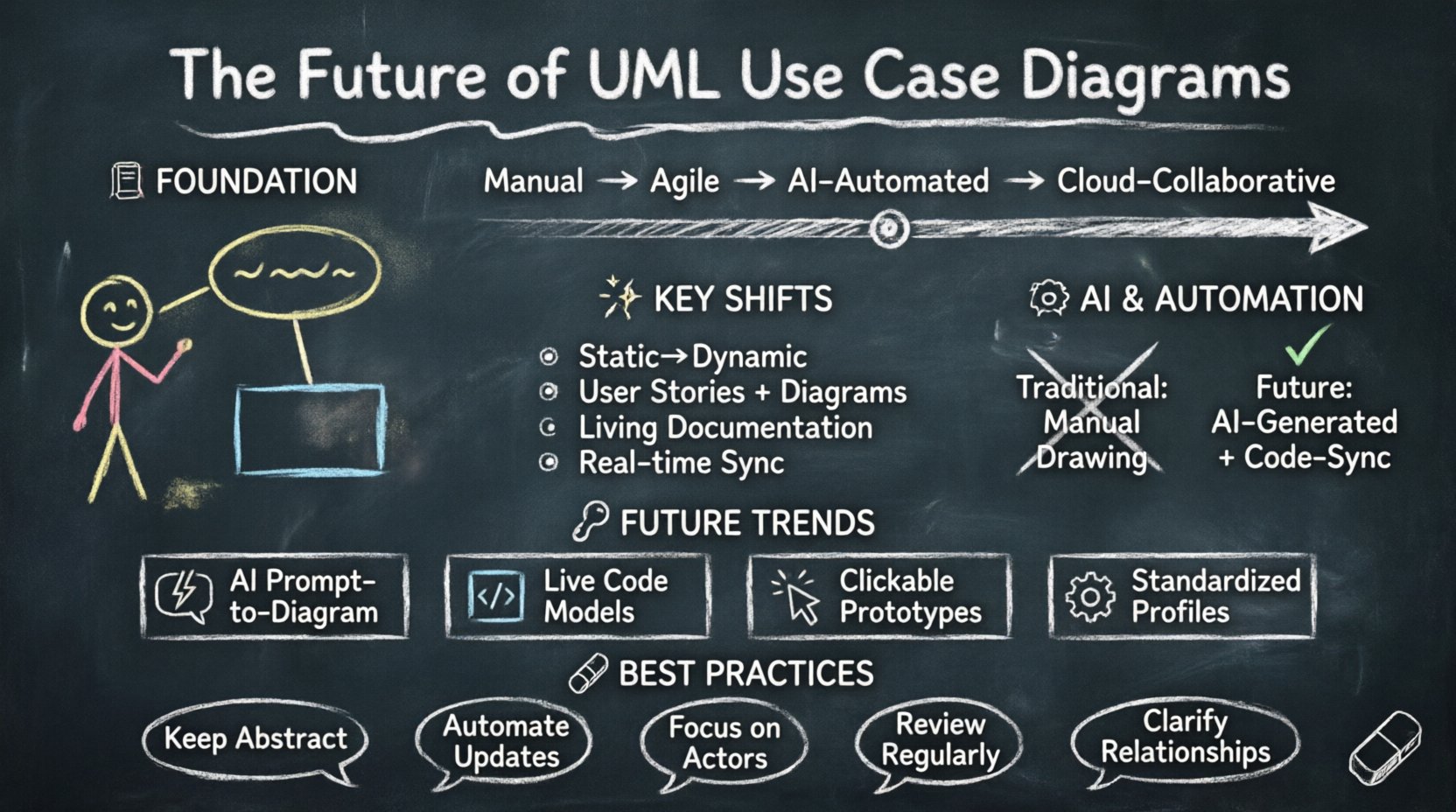
📜 The Foundation of UML Use Case Diagrams
Before projecting forward, it is necessary to understand the core mechanics of the Use Case Diagram. It is a behavioral diagram that illustrates the interactions between actors and the system. These interactions represent the functional requirements that the system must satisfy.
Traditionally, these diagrams served as the bridge between business stakeholders and technical architects. They provided a high-level abstraction that allowed non-technical users to understand what the system would do without delving into the complexities of code.
- Actors: Represented as stick figures, these denote roles such as users, external systems, or hardware devices.
- Use Cases: Ovals representing specific functions or goals the actor can achieve.
- Relationships: Lines connecting actors to use cases, indicating association, inclusion, or extension.
- System Boundary: A rectangle defining the scope of the software.
In the past, creating these diagrams was a manual process. Architects would spend weeks drafting these models in isolation before a single line of code was written. This approach worked well for waterfall methodologies but struggled to keep pace with iterative development cycles.
🚀 Shifts in Methodology: Agile and DevOps Impact
The rise of Agile and DevOps has fundamentally changed how documentation is treated. In high-velocity environments, heavy upfront modeling can become a bottleneck. The question is no longer whether to model, but how to model efficiently.
From Static to Dynamic
Legacy modeling often produced static artifacts that were rarely updated after the design phase. Modern development requires diagrams that evolve alongside the codebase. This shift demands a more integrated approach where diagrams are generated from or synchronized with the system state.
The Role of User Stories
Many teams have replaced traditional Use Case Diagrams with User Stories in Agile frameworks. While User Stories capture requirements effectively, they lack the visual representation of system boundaries and actor interactions that Use Case Diagrams provide. The future lies in a hybrid approach.
- Agile Integration: Using diagrams to visualize the scope of a sprint backlog.
- Backlog Mapping: Linking high-level use cases to specific stories for traceability.
- Living Documentation: Ensuring the diagram reflects the current state of the application.
🤖 Automation and AI in Diagram Generation
One of the most significant evolutions in the future of UML Use Case Diagrams is the integration of automation. Manual drawing is prone to error and inconsistency. Automated tools can extract requirements from text or code to generate initial models.
Natural Language Processing (NLP)
Advancements in NLP allow systems to parse requirements documents, emails, or meeting transcripts to identify actors and actions. This capability reduces the time spent on manual diagramming.
- Requirement Parsing: Algorithms identify verbs as potential use cases and nouns as potential actors.
- Relationship Inference: AI can suggest standard relationships like include or extend based on context.
- Consistency Checking: Automated validation ensures that all actors have paths to meaningful use cases.
Code-to-Model Synchronization
As software becomes more complex, maintaining a diagram manually is increasingly difficult. Reverse engineering tools can scan the codebase to update diagrams automatically. This ensures that the documentation never drifts too far from the implementation.
| Feature | Traditional Approach | Automated Future Approach |
|---|---|---|
| Creation | Manual drawing | AI-assisted generation |
| Updates | Periodic revision | Real-time synchronization |
| Accuracy | Prone to human error | Derived from source truth |
| Effort | High maintenance cost | Low overhead |
🔗 Integration with Modern Design Patterns
Modern software architecture relies heavily on patterns like Microservices, Event-Driven Architecture, and Serverless computing. These patterns introduce complexity that traditional Use Case Diagrams were not designed to handle. The diagrams must evolve to represent distributed actors and asynchronous interactions.
Modeling Distributed Actors
In a monolithic system, the system boundary is clear. In a microservices environment, the “system” is a collection of services. Use Case Diagrams must adapt to show external services as actors or nested systems.
- Service Boundaries: Clearly defining which service owns which use case.
- API Contracts: Treating API endpoints as use cases in their own right.
- Third-Party Integration: Visualizing external dependencies as distinct actors.
Asynchronous Interactions
Traditional use cases imply a synchronous request-response flow. Modern systems often rely on event queues and background processing. Future diagrams may need to incorporate symbols or annotations to denote asynchronous triggers and eventual consistency.
🌐 Collaboration and Real-time Modeling
The way teams work has changed. Remote collaboration is now standard. Documentation tools must support real-time co-authoring and version control integration.
Cloud-Based Modeling
Local file storage is becoming obsolete for modeling tools. Cloud-based platforms allow multiple stakeholders to view and edit diagrams simultaneously. This reduces the friction between designers, developers, and product managers.
- Real-time Editing: Multiple users working on the same diagram.
- Commenting Systems: Contextual feedback directly on diagram elements.
- Version History: Tracking changes to understand the evolution of requirements.
Integration with Project Management
For diagrams to remain relevant, they must be linked to the work items that drive development. Integration with task tracking systems ensures that every use case is accounted for in the sprint planning process.
⚠️ Challenges and Limitations
Despite the potential for evolution, there are significant hurdles to overcome. The utility of a diagram depends entirely on its maintenance and relevance.
Complexity Management
As systems grow, diagrams can become cluttered and unreadable. There is a risk that detailed diagrams become too complex to be useful. Future approaches must focus on abstraction levels, allowing users to drill down from high-level business goals to technical implementation details.
Adoption Barriers
Even with automation, teams may resist formal modeling if it feels like overhead. The value proposition must be clear. Diagrams should aid decision-making, not just satisfy compliance.
- Just-in-Time Modeling: Creating diagrams only when necessary for a specific discussion.
- Visual Clarity: Prioritizing readability over completeness.
- Tooling Friction: Ensuring the modeling tool does not disrupt the workflow.
🔮 Future Scenarios and Trends
Looking ahead, several specific trends will shape the next decade of UML Use Case Diagrams. These scenarios represent the likely path of adoption and technological integration.
| Trend | Description | Impact on Use Case Diagrams |
|---|---|---|
| AI-Driven Modeling | Generative AI creates diagrams from text prompts. | Reduced manual effort, faster prototyping. |
| Live Code Models | Diagrams update automatically from source code. | High accuracy, reduced technical debt in docs. |
| Interactive Prototypes | Diagrams become clickable simulations. | Enhanced stakeholder understanding. |
| Standardization | Industry-wide adoption of extended UML profiles. | Better interoperability between tools. |
🛠 Best Practices for the Next Decade
To remain effective, architects and developers should adopt specific practices that align with the evolving landscape. These guidelines ensure that the diagrams serve their purpose without becoming a burden.
- Maintain Abstraction: Keep high-level diagrams focused on business value. Do not clutter them with technical implementation details.
- Automate Where Possible: Utilize scripts and plugins to update diagrams from code repositories.
- Focus on Actors: Ensure every actor has a clear value proposition within the system context.
- Regular Reviews: Treat diagrams as living documents that require periodic validation against the actual system.
- Contextualize Relationships: Clearly define why actors interact with specific use cases. Avoid unnecessary connections.
📊 The Role of Model-Driven Architecture
Model-Driven Architecture (MDA) proposes that models are the primary artifacts from which code is generated. While full code generation is not yet the norm, the concept influences how diagrams are structured. The focus shifts from drawing pictures to defining executable specifications.
In this context, a Use Case Diagram is not just a drawing; it is a specification of behavior. This elevates the importance of precision. Ambiguity in the diagram can lead to ambiguity in the generated logic.
- Precision: Defining preconditions and postconditions for use cases.
- Traceability: Linking model elements directly to code units.
- Validation: Using formal methods to verify that the model matches the requirements.
🎯 Balancing Detail and Usability
A common pitfall in system design is over-engineering the documentation. The future of UML Use Case Diagrams depends on finding the right balance between detail and usability. Teams must decide when a diagram adds value and when it adds noise.
For new projects, a high-level Use Case Diagram is essential for alignment. For existing projects, the diagram should be maintained only if it aids in understanding complex flows or onboarding new team members. If the code is self-documenting, the diagram may become redundant.
Consider the following criteria before updating a diagram:
- Does the system behavior change significantly?
- Is there confusion among stakeholders regarding a specific feature?
- Is the diagram required for a specific compliance or audit requirement?
- Will the diagram help in onboarding a new developer?
🌟 The Human Element in Modeling
Despite the rise of AI and automation, the human element remains central to modeling. Diagrams are communication tools, not just technical artifacts. They facilitate conversation between business owners and technical teams.
The evolution of the Use Case Diagram is not just about technology; it is about how people collaborate. Tools that support better communication will thrive. Tools that simply generate pretty pictures without enabling discussion will fade.
- Facilitation: Using diagrams as a focal point for requirements workshops.
- Translation: Bridging the gap between business language and technical logic.
- Consensus: Ensuring all parties agree on the system boundaries and scope.
🏁 Summary of the Evolution
The UML Use Case Diagram is not disappearing, but it is maturing. It is moving from a static, manual artifact to a dynamic, automated component of the development lifecycle. The integration of AI, the shift towards cloud collaboration, and the demands of microservices architecture are driving this change.
Teams that embrace these changes will find that diagrams remain a powerful tool for clarity and alignment. Those that cling to outdated manual processes will find their documentation becoming stale and disconnected from reality.
The future is collaborative, automated, and integrated. By focusing on value, precision, and maintenance, the Use Case Diagram will continue to play a vital role in shaping modern software systems.
Keep the diagrams simple. Keep them updated. Let them serve the team, not the other way around. This pragmatic approach ensures that the modeling effort remains a strategic advantage rather than a bureaucratic hurdle.
As technology continues to advance, the principles of clear communication and structured thinking will remain constant. The UML Use Case Diagram, in its evolved form, will continue to be a key instrument in achieving those goals.