
Legacy systems often become the silent engines of an organization, running critical operations without clear documentation or modern architectural patterns. When new engineers join a team or maintenance becomes necessary, the lack of visibility into system behavior creates significant risk. One of the most effective ways to bring clarity to complex, event-driven legacy applications is through the creation of UML State Machine Diagrams. This approach transforms opaque code into a visual map of logic, making it easier to understand, test, and refactor.
Documentation is not merely about drawing pictures; it is about capturing the behavior of the software. While static analysis shows structure, dynamic analysis reveals how the system reacts to inputs over time. This guide details the systematic process of reverse engineering legacy code into precise state diagrams, ensuring that future modifications do not break existing functionality.
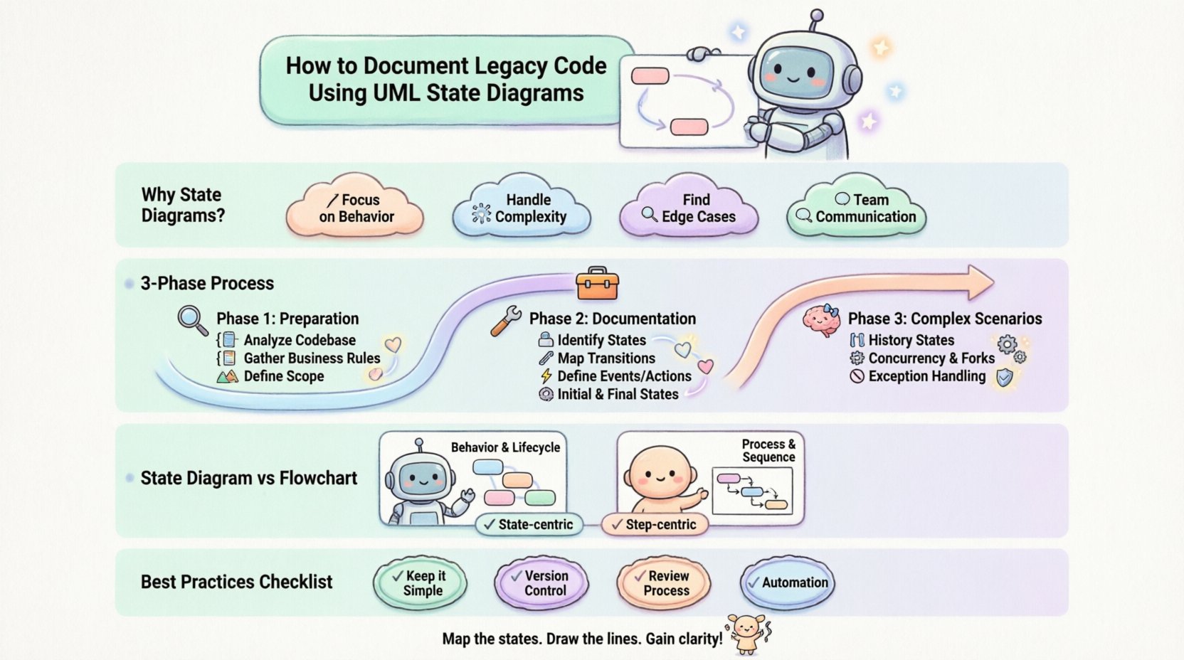
🧩 Why State Diagrams for Legacy Systems?
Legacy code often suffers from spaghetti logic or deeply nested conditionals that are difficult to trace. State diagrams offer a structured alternative to linear flowcharts. Here is why they are particularly suited for this task:
- Focus on Behavior: They describe what the system does in response to events, rather than just the sequence of instructions.
- Handling Complexity: They allow for the modeling of concurrent activities and complex decision points without cluttering the visual flow.
- Identifying Edge Cases: The process of defining states forces the engineer to consider what happens when no event matches, or when an invalid transition occurs.
- Communication: They serve as a universal language for developers, testers, and stakeholders to discuss system behavior.
Unlike sequence diagrams which focus on object interaction over time, state diagrams focus on the lifecycle of a single object or component. This makes them ideal for modeling the internal logic of a service, a user session, or a payment transaction.
🔍 Phase 1: Preparation and Discovery
Before drawing a single box or arrow, you must gather information. Attempting to model a system without understanding its context leads to inaccurate diagrams. This phase involves reverse engineering the codebase and observing runtime behavior.
📂 Analyze the Codebase
Start by searching for patterns that indicate state management. Look for:
- Enum Definitions: Variables that hold a single value from a set (e.g.,
status = PENDING). - Conditional Blocks: Large
switchorif-elsestructures that change logic based on a specific variable. - Event Handlers: Functions triggered by specific inputs or messages.
- Global Variables: Flags that persist across function calls and influence logic flow.
📝 Gather Business Rules
Code often implements business logic that is not immediately obvious. Review:
- User Stories: How do users expect the system to behave?
- Logs: Analyze historical logs to see the sequence of events that occur in production.
- Database Triggers: Check for database-level logic that might alter the state of records independently of the application.
🗺️ Define the Scope
Do not attempt to model the entire system at once. Break it down into manageable components. A good rule of thumb is to focus on one distinct entity per diagram. For example, model the Order object separately from the Payment object.
| Component | State Complexity | Priority |
|---|---|---|
| Payment Processor | High (Critical Flow) | 1 |
| Session Management | Medium (User Experience) | 2 |
| Logging Service | Low (Internal Utility) | 3 |
🛠️ Phase 2: The Documentation Process
Once the scope is defined, begin the actual modeling. This process requires translating code logic into visual symbols. Follow these steps to ensure accuracy.
🟦 Step 1: Identify States
A state represents a condition or situation during the life of an object when it satisfies some condition, performs some action, or waits for some event. In legacy code, these are often stored in variables.
- Explicit States: Values defined in the code (e.g.,
state = 'Active'). - Implicit States: Logic derived from the absence of other conditions (e.g.,
if (state != 'Closed')implies'Open'). - Composite States: A state that contains sub-states. If a legacy component handles multiple sub-processes, group them logically.
Tip: Give states meaningful names. Avoid generic names like State1 or ProcessA. Use domain-specific terminology like OrderProcessed or InvoiceSent.
🔗 Step 2: Map Transitions
Transitions represent the change of state from one condition to another. They are triggered by events.
- Triggers: Identify what causes the change. Is it a user action? A timer? A database update?
- Guards: These are conditions that must be true for the transition to occur. For example, a transition from
PaymentPendingtoPaymentSuccessmight have a guard[fundsAvailable]. - Actions: What happens during the transition? Often, this involves calling a function or sending a message.
⚡ Step 3: Define Events and Actions
Not every line of code is a state transition. Focus on the when and what.
- Entry Actions: Code executed when entering a state (e.g., initializing a variable).
- Exit Actions: Code executed when leaving a state (e.g., cleaning up resources).
- Do Activities: Continuous actions performed while in a state (e.g., polling a sensor).
🏁 Step 4: Identify Initial and Final States
Every state machine needs a starting point and a logical end.
- Initial State: Represented by a solid black circle. This is where the lifecycle begins.
- Final State: Represented by a solid black circle inside a circle. This indicates the object has completed its lifecycle.
🧠 Phase 3: Handling Complex Scenarios
Legacy code often contains patterns that do not fit neatly into simple diagrams. You must decide how to represent these complexities accurately.
🔄 History States
When a system returns to a composite state, it often needs to remember where it left off. Use Deep History or Shallow History states to capture this behavior. This prevents the need to model every possible return path explicitly.
⚙️ Concurrency and Forks
If a legacy system handles multiple tasks simultaneously (e.g., logging and saving data), use Fork and Join bars. A fork splits the flow into parallel states, while a join waits for all parallel paths to complete before continuing.
🚫 Exception Handling
Legacy systems often have hidden error states. Ensure your diagram accounts for:
- What happens if an expected event does not arrive?
- Where do exceptions get caught and how are they logged?
- Is there a recovery path back to a stable state?
📊 Comparison: State Diagram vs. Flowchart
Engineers sometimes confuse state diagrams with flowcharts. Understanding the difference is crucial for documentation.
| Feature | State Diagram | Flowchart |
|---|---|---|
| Focus | Behavior and Lifecycle | Process and Sequence |
| Context | Remembers current state | Linear path |
| Complexity | Good for branching logic | Good for simple algorithms |
| Reusability | States can be shared | Paths are specific |
🚧 Common Challenges in Legacy Contexts
Documenting old code presents unique hurdles. Be aware of these common pitfalls.
🕸️ Hidden State
State is sometimes stored in global variables or database rows that are not obvious from the code structure. You must trace the data flow to find the true source of truth.
🧩 Global Variables
Legacy code often relies on mutable global state. This makes the behavior of a function dependent on the environment, not just its inputs. Document these dependencies clearly in the diagram notes.
📉 Code Drift
The code may have diverged from the original design. The diagram should reflect the current reality, not the intended design. If the code has been patched over years, the state machine is likely the most accurate source of truth.
🛡️ Best Practices for Maintenance
A diagram is useless if it becomes outdated immediately. Integrate documentation into the development lifecycle.
- Keep it Simple: Avoid over-documenting. If a state has no transitions, it does not exist.
- Version Control: Store diagram files alongside the code they represent.
- Review Process: Require state diagram updates during code reviews for significant logic changes.
- Automation: If possible, generate diagrams from code annotations or run tests to validate the states.
📋 Documentation Checklist
Before considering a state diagram complete, verify the following:
- All States Defined: Every possible condition the object can be in is represented.
- All Transitions Covered: There are no “dead ends” unless intentional.
- Events Mapped: Every input that causes a change is listed.
- Actions Described: Side effects of transitions are noted.
- Error Handling: Invalid inputs are handled (e.g., self-loops with error messages).
- Consistency: Naming conventions match the codebase.
🔄 Moving Forward
Creating UML State Diagrams for legacy code is an investment in stability. It reduces the cognitive load on new team members and provides a safety net for refactoring efforts. By systematically identifying states, mapping transitions, and accounting for edge cases, you transform a black box into a transparent system.
Remember that documentation is a living artifact. It requires maintenance just like the code itself. As the system evolves, the diagram must evolve with it. This continuous alignment ensures that the technical debt does not accumulate in the form of undocumented logic, keeping the system robust and understandable for years to come.
Start with the most critical path. Map the states. Draw the lines. The clarity you gain will pay dividends in every future sprint.