
Understanding how systems behave over time is a critical skill in software engineering and systems design. A UML State Machine Diagram, often referred to as a State Diagram, provides a visual representation of the lifecycle of an object. It captures the dynamic behavior of a system, detailing how it reacts to various events. This guide offers a structured approach to learning this modeling technique through practical, interactive exercises.
Many professionals struggle with the nuance of defining states versus transitions. Simply drawing boxes and arrows is not enough; the logic must be precise. The following sections present scenarios designed to deepen your comprehension of state modeling. You will move from simple logic to complex hierarchical structures without relying on specific tools.
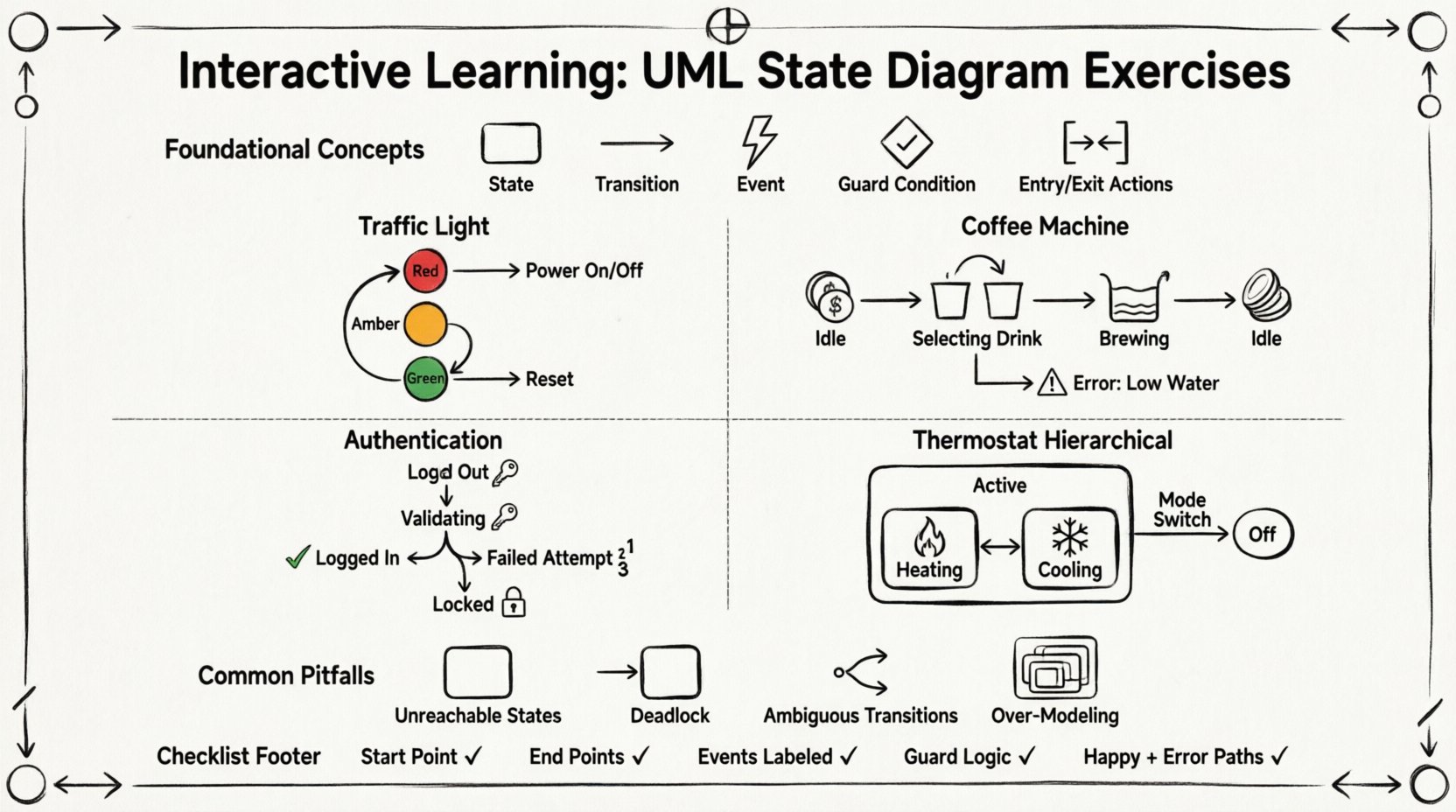
Foundational Concepts for State Modeling 🧠
Before diving into exercises, it is essential to align on the core vocabulary. A state diagram models the behavior of a single object or a system component. It answers the question: “What happens when this entity receives a specific input?”
- State: A condition or situation during the life of an object during which it satisfies some condition, performs some activity, or waits for some event.
- Transition: A relationship between two states indicating that objects in the source state will move to the destination state when a specified event occurs.
- Event: A significant occurrence in space and time that may cause a transition. Examples include user clicks, timer expirations, or external signals.
- Guard Condition: A Boolean expression that must be true for the transition to occur.
- Entry/Exit Actions: Activities performed when entering or leaving a state.
Accuracy in these definitions prevents ambiguity. A transition without an event is invalid. A state without a valid path to a final state may represent a deadlock.
Exercise 1: The Traffic Light Controller 🚦
This scenario is ideal for beginners. It focuses on sequential transitions and basic event handling. The goal is to model a simple intersection traffic light.
Scenario Requirements
- The system starts in a “Off” state.
- A “Power On” event activates the light.
- The light cycles through Red, Amber, and Green.
- A “Reset” event immediately returns the system to Red.
- The system can be turned “Off” at any time.
Modeling Steps
- Identify States: List the distinct conditions. You will likely need: Off, Red, Amber, Green.
- Define Initial State: The system begins at Off (or a pseudo-state that leads to Red).
- Map Transitions: Connect the states based on the requirements above.
- Assign Events: Label the arrows with Power On, Timer Expired, Reset, Power Off.
Validation Checklist
| Check | Criteria |
|---|---|
| Completeness | Can every state be reached from the start? |
| Reachability | Can every state reach the final or off state? |
| Clarity | Is there only one path for a specific event from a state? |
In this exercise, ensure you handle the “Reset” event correctly. Does it happen from Amber? From Green? The diagram must show explicit transitions for the reset action from every active state, or use a signal that broadcasts to all states.
Exercise 2: The Coffee Machine ☕
This scenario introduces complexity through error handling and wait states. It mimics a real-world embedded system where user interaction must be managed carefully.
Scenario Requirements
- The machine has a Idle state waiting for coin insertion.
- Once coins are inserted, it moves to Selecting Drink.
- The user selects a drink (e.g., Espresso, Latte).
- The machine enters a Brewing state.
- If the water tank is empty, it must go to Error: Low Water.
- After brewing, it returns to Idle.
Key Modeling Decisions
When modeling the brewing process, consider the duration. Is brewing a state, or is it an action within a transition? In UML, if the system waits for a specific duration, it is often better modeled as a state.
- State: Brewing. Entry Action: Start heating element. Exit Action: Turn off heater.
- Transition: Brewing to Idle (Event: Brew Complete).
- Guard: If water level > 0.
- Alternative Transition: Brewing to Error (Event: Low Water).
Handling Timeouts
What happens if the user does not select a drink within 30 seconds? This requires a timeout event. You can add a transition from Selecting Drink back to Idle labeled Timeout.
This exercise highlights the importance of defining what happens when things go wrong. A robust diagram accounts for exceptions, not just the happy path.
Exercise 3: User Authentication System 🔐
Security systems require precise state management. This exercise deals with login attempts, account locking, and session management.
Scenario Requirements
- User starts at Logged Out.
- Upon entering credentials, the system moves to Validating.
- If valid, move to Logged In.
- If invalid, move to Login Failed.
- If three invalid attempts occur, the account locks to Locked.
- From Locked, the user must contact support or wait for a reset.
Complex Transitions
Here, you must manage a counter. While state diagrams do not typically store counters explicitly, the state Login Failed implies a state where the count is tracked. You might need to split Login Failed into Failed Attempt 1, Failed Attempt 2, etc., to visualize the logic clearly without external variables.
| State | Event | Next State | Guard Condition |
|---|---|---|---|
| Logged Out | Submit Credentials | Validating | None |
| Validating | Auth Success | Logged In | None |
| Validating | Auth Failure | Failed Attempt 1 | Attempts < 3 |
| Failed Attempt 2 | Auth Failure | Locked | Attempts = 3 |
This level of detail ensures developers understand the exact logic required for the authentication module.
Exercise 4: Hierarchical States (Composite States) 📦
As systems grow, flat diagrams become messy. UML supports composite states. This exercise teaches you how to nest states within states.
Scenario: Smart Home Thermostat
The thermostat has a main state of Active. Within Active, there are sub-states for heating and cooling. It also has a main state of Off.
Modeling the Hierarchy
- Create a large box representing the Active state.
- Inside this box, place Heating and Cooling states.
- Define transitions between Heating and Cooling based on temperature sensors.
- Define a transition from Heating to Cooling if the temperature exceeds the set point.
- Add a transition from the outer Active box to Off when the user changes the mode.
Deep vs. Shallow History
When returning to a composite state, what is the initial condition?
- Shallow History: Returns to the initial sub-state of the composite state.
- Deep History: Returns to the last active sub-state before leaving.
Deciding which history mechanism to use is a critical design choice. For a thermostat, you might want Deep History so it resumes exactly where it left off after a power cycle.
Common Pitfalls in State Diagrams ⚠️
Even experienced modelers encounter issues. Reviewing these common errors can save time during the design phase.
1. Unreachable States
If a state cannot be entered from any other state, it is useless code. Review your initial state and ensure every defined state is reachable via a valid path.
2. Deadlocks
A deadlock occurs when the system reaches a state where no events are defined to transition out. Ensure every state has at least one outgoing transition unless it is a final state.
3. Ambiguous Transitions
From a single state, if two transitions are triggered by the same event, the model is ambiguous. You must use guard conditions to differentiate the paths.
4. Over-Modeling
Not every detail needs a state. If an action happens instantly, it does not need its own state box. Keep the diagram focused on the significant conditions of the system.
Self-Assessment Checklist ✅
Before considering a diagram complete, run it through this audit.
- Start Point: Is there a single initial state (black circle)?
- End Points: Are there final states (double circle) where appropriate?
- Events: Is every transition labeled with a triggering event?
- Logic: Do guard conditions cover all scenarios?
- Consistency: Are state names consistent across the diagram?
- Completeness: Does the diagram cover the happy path and error paths?
Integration with System Design 🛠️
Once the diagram is finalized, it serves as a blueprint for implementation. Developers use these models to write state machines in code. The clarity of your diagram directly impacts the maintainability of the software.
Documentation
Include a legend explaining symbols used. If you use custom notations for specific events, document them. This ensures that anyone reading the diagram understands the context without needing prior knowledge of the specific project.
Testing Alignment
Use the transitions as test cases. Each transition represents a potential test scenario. If a transition exists in the diagram, a test case should exist to verify that transition occurs as expected under the specified conditions.
Final Considerations for Continuous Improvement 🚀
State modeling is a skill that improves with practice. Start with simple objects like a light switch and gradually move to complex workflows. The goal is not just to draw boxes, but to think logically about the lifecycle of your data and objects.
Regularly revisit your diagrams. As requirements change, the diagram must evolve. A static diagram becomes a liability if the system it represents changes. Treat the state diagram as a living document.
By working through these exercises, you build an intuition for how systems behave. This intuition is invaluable when designing robust, reliable software architectures. Focus on clarity, precision, and completeness in every model you create.