
Creating a clear visual representation of system behavior is a critical skill in software engineering. One of the most effective tools for this is the UML Use Case Diagram. However, translating text-based user requirements into these diagrams can be challenging. This guide provides a structured approach to mapping requirements accurately.
Many teams struggle with the gap between written specifications and visual models. Without a systematic method, diagrams can become cluttered or miss key functionalities. By following a disciplined process, you ensure that every stakeholder need is captured visually. This document outlines the steps to bridge that gap effectively.
🎯 Understanding the Goal of Use Case Diagrams
A Use Case Diagram serves as a high-level view of system functionality. It answers the question: “Who interacts with the system, and what do they do?” It does not detail the internal logic or code structure. Instead, it focuses on external interactions.
When mapping requirements, the objective is to ensure no user need is left out and no feature is added without justification. This alignment prevents scope creep and ensures development efforts match stakeholder expectations.
- Focus on Behavior: The diagram describes what the system does, not how it does it.
- Identify Actors: Determine who or what initiates the interaction.
- Define Use Cases: Capture the specific goals achieved by the actor.
- Set Boundaries: Clearly define what is inside the system and what is outside.
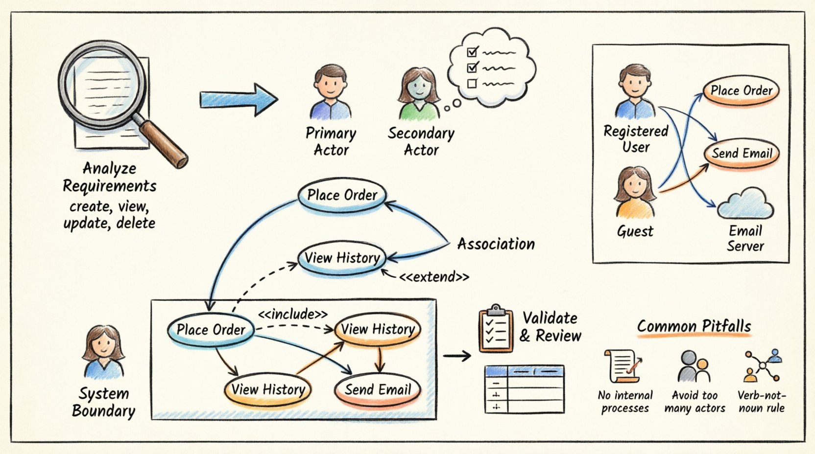
📝 Step 1: Analyzing User Requirements
Before drawing a single line, you must thoroughly review the requirement documentation. This phase involves reading functional and non-functional requirements to identify actionable items.
Identifying Action Verbs
Use cases are essentially actions. Scan your requirement documents for verbs. Words like “create,” “view,” “update,” “delete,” or “send” often signal a potential use case.
- Functional Requirements: These describe specific behaviors. Example: “The system shall allow users to reset their password.”
- Action: Reset Password
- Non-Functional Requirements: These describe quality attributes like performance or security. While not always direct use cases, they often constrain them. Example: “The system must respond within 2 seconds.”
- Implication: Performance monitoring use case or system health check.
Categorizing Requirements
Group your requirements to see patterns. This helps in identifying distinct actors. You might find a cluster of requirements related to “Admins” and another for “Guests.” This separation is the foundation for defining actors.
👥 Step 2: Identifying Actors
An actor represents a role played by an external entity that interacts with the system. It is crucial to distinguish between the person and the role. One person can play multiple roles, and one role can be played by multiple people.
Types of Actors
- Primary Actors: Those who initiate the use case to achieve a goal. Example: A customer starting a purchase.
- Secondary Actors: Those who provide services to the system. Example: A payment gateway or an external email server.
Actor Identification Checklist
Ask the following questions to verify if an entity is an actor:
- Does the entity initiate a goal?
- Is the entity outside the system boundary?
- Does the entity send data to or receive data from the system?
- Would the system function differently without this entity?
Do not include internal system components as actors. For instance, a database or a report generator module is part of the system, not an external actor.
🔄 Step 3: Defining Use Cases
Once actors are defined, map the requirements to specific use cases. A use case is a complete unit of functionality that provides value to an actor.
Writing Use Case Titles
Titles should follow a verb-object format. This creates clarity and consistency across the diagram.
- Correct: “Place Order,” “Search Product,” “Update Profile.”
- Incorrect: “Ordering,” “Search,” “Profile Management.”
Refining Scope
Ensure each use case is atomic. If a use case contains too many steps, it might be better split into smaller use cases. Conversely, if a use case is too trivial, it might be merged.
Example Mapping
Consider a requirement: “The user must be able to view their order history.”
- Actor: Registered User
- Use Case: View Order History
- Goal: The user wants to see past transactions.
🔗 Step 4: Establishing Relationships
Use cases and actors are connected by associations. Additionally, use cases can relate to each other. Understanding these relationships is vital for accurate modeling.
Association
This is a simple line connecting an actor to a use case. It indicates that the actor interacts with that use case.
Include Relationship
An <<include>> relationship means one use case incorporates the behavior of another. It is mandatory. The base use case cannot complete without the included use case.
- Example: “Place Order” includes “Confirm Payment.”
- Logic: You cannot place an order without confirming payment.
Extend Relationship
An <<extend>> relationship means one use case adds behavior to another under specific conditions. It is optional.
- Example: “Place Order” is extended by “Apply Discount Code.”
- Logic: You can place an order without a discount code, but the option exists.
📐 Step 5: Defining the System Boundary
The system boundary is a rectangle that encloses the use cases. Everything inside is part of the system. Everything outside is part of the environment.
Placement Rules
- Actors must always be placed outside the boundary.
- Use cases must be placed inside the boundary.
- Lines crossing the boundary represent data flow between actor and system.
Defining this clearly helps developers understand what needs to be built versus what exists externally.
📊 Mapping Requirements to Diagram Elements
The following table illustrates how to translate text requirements into visual elements. This serves as a reference during the modeling process.
| Requirement Type | Text Example | Diagram Element | Relationship |
|---|---|---|---|
| Functional Action | “System sends email confirmation.” | Use Case: Send Confirmation | Include (if mandatory) |
| User Role | “Admins can generate reports.” | Actor: Admin | Association |
| Conditional Logic | “If balance is low, notify user.” | Use Case: Notify User | Extend (from Check Balance) |
| External Dependency | “System connects to Bank API.” | Actor: External Bank | Association |
| Non-Functional Constraint | “Response time < 1s.” | System Boundary Note | None (Constraint) |
🛠️ Step 6: Validation and Review
Once the diagram is drafted, it must be validated against the original requirements. This step ensures fidelity and completeness.
Traceability Matrix
Create a simple list that maps each requirement ID to the Use Case ID. This ensures every requirement has a visual counterpart.
- Requirement ID: FR-001 ➔ Use Case ID: UC-01
- Requirement ID: FR-002 ➔ Use Case ID: UC-02
Stakeholder Verification
Present the diagram to the business owners or stakeholders. Ask them to confirm if the visual model matches their mental model of the system.
🧪 Practical Example: E-Commerce System
To visualize the process, consider a simplified E-Commerce scenario. We will walk through the requirements and the resulting diagram structure.
Scenario Requirements
- User can register for an account.
- User can browse products.
- User can add items to a cart.
- Guest can check out.
- Registered user can track orders.
- System must send an email upon order placement.
Analysis
From requirement 1 and 5, we identify the “Registered User” actor. From requirement 4, we identify the “Guest” actor. Requirement 6 implies an external actor or a system process, often modeled as an external email service actor.
Diagram Structure
- Actor: Registered User
- Register Account
- Browse Products
- Add to Cart
- Track Orders
- Actor: Guest
- Checkout (as Guest)
- Actor: Email Server
- Receive Order Confirmation (Included in Checkout)
Refining Relationships
Both “Registered User” and “Guest” perform a checkout action. This can be generalized. However, for simplicity in a basic diagram, separate use cases might be clearer to distinguish data requirements (login vs. no login).
The “Email Server” actor connects to the “Checkout” use case. This connection is an association. The “Send Email” function is an included use case within “Checkout.” This ensures the logic is modular.
⚠️ Common Pitfalls to Avoid
Even with a clear process, mistakes can happen. Be aware of these common issues when mapping requirements.
1. Modeling Internal Processes
Do not draw use cases for internal steps like “Validate Input” or “Calculate Tax” unless they are directly visible to the user. These are implementation details.
2. Too Many Actors
Creating too many actors fragments the diagram. If multiple users perform the same tasks, group them under a generic role like “Customer” or “User.”
3. Confusing Data with Actions
A use case is a verb phrase, not a noun. “Product” is a data entity. “Browse Product” is the action. Ensure all diagram nodes represent actions.
4. Ignoring Non-Functional Needs
While non-functional requirements do not always become use cases, they should be noted. For example, security requirements might imply an “Authenticate” use case that is hidden or part of a login process.
5. Overusing Include/Extend
Do not create a chain of includes. If a use case includes another, which includes a third, simplify the diagram. Use cases should be manageable units of value.
🚀 Best Practices for Maintenance
Requirements change. The diagram must evolve with them. Treat the diagram as a living document.
- Version Control: Keep a history of diagram versions. This helps track how the system scope changed over time.
- Annotations: Use notes to explain complex logic that cannot be shown with lines.
- Consistency: Use the same naming conventions for actors and use cases across all diagrams in the project.
- Regular Reviews: Schedule reviews of the diagrams during sprint planning or requirement updates.
🔍 Ensuring Clarity and Readability
A diagram is useless if no one understands it. Layout matters as much as content.
- Group Related Use Cases: Place related functions near each other.
- Minimize Line Crossings: Arrange actors and use cases to reduce tangled lines.
- Label Associations: Add labels to lines if the relationship is not obvious (e.g., “Uses,” “Manages”).
- White Space: Leave space between elements to avoid clutter.
Remember that the diagram is a communication tool. Its primary audience includes developers, testers, and business stakeholders. It must be readable by all.
📈 Measuring Success
How do you know your mapping was successful? Look for these indicators.
- Traceability: Every requirement has a corresponding use case.
- Completeness: No major functionality is missing from the visual model.
- Clarity: A new team member can understand the system flow from the diagram alone.
- Accuracy: The development team builds what is depicted without confusion.
📝 Summary of Workflow
To recap the entire process, follow this sequence.
- Gather Requirements: Collect all functional and non-functional specs.
- Extract Actors: Identify who interacts with the system.
- Define Use Cases: Map requirements to action-based use cases.
- Draw Relationships: Connect actors to use cases and use cases to each other.
- Set Boundaries: Define the system perimeter.
- Validate: Check against original requirements and stakeholder feedback.
By adhering to this workflow, you create diagrams that are not just technical drawings but valuable blueprints for development. This approach reduces ambiguity and aligns technical delivery with business needs.
Consistent application of these principles leads to robust system designs. The effort invested in accurate mapping pays dividends during the development and testing phases. It prevents rework and ensures the final product meets the intended goals.
Start with the requirements, respect the actors, and keep the focus on user value. This is the core of effective UML Use Case modeling.