
In the competitive landscape of technical hiring, visual communication often distinguishes a candidate from the rest. A UML Use Case Diagram serves as a bridge between abstract requirements and concrete system behavior. It demonstrates your ability to think in terms of actors, interactions, and boundaries. This guide provides a deep dive into constructing a high-quality diagram suitable for your portfolio and technical interviews. We will explore the structural elements, logical relationships, and presentation strategies without relying on specific proprietary tools.
Why These Diagrams Matter in Technical Interviews 💡
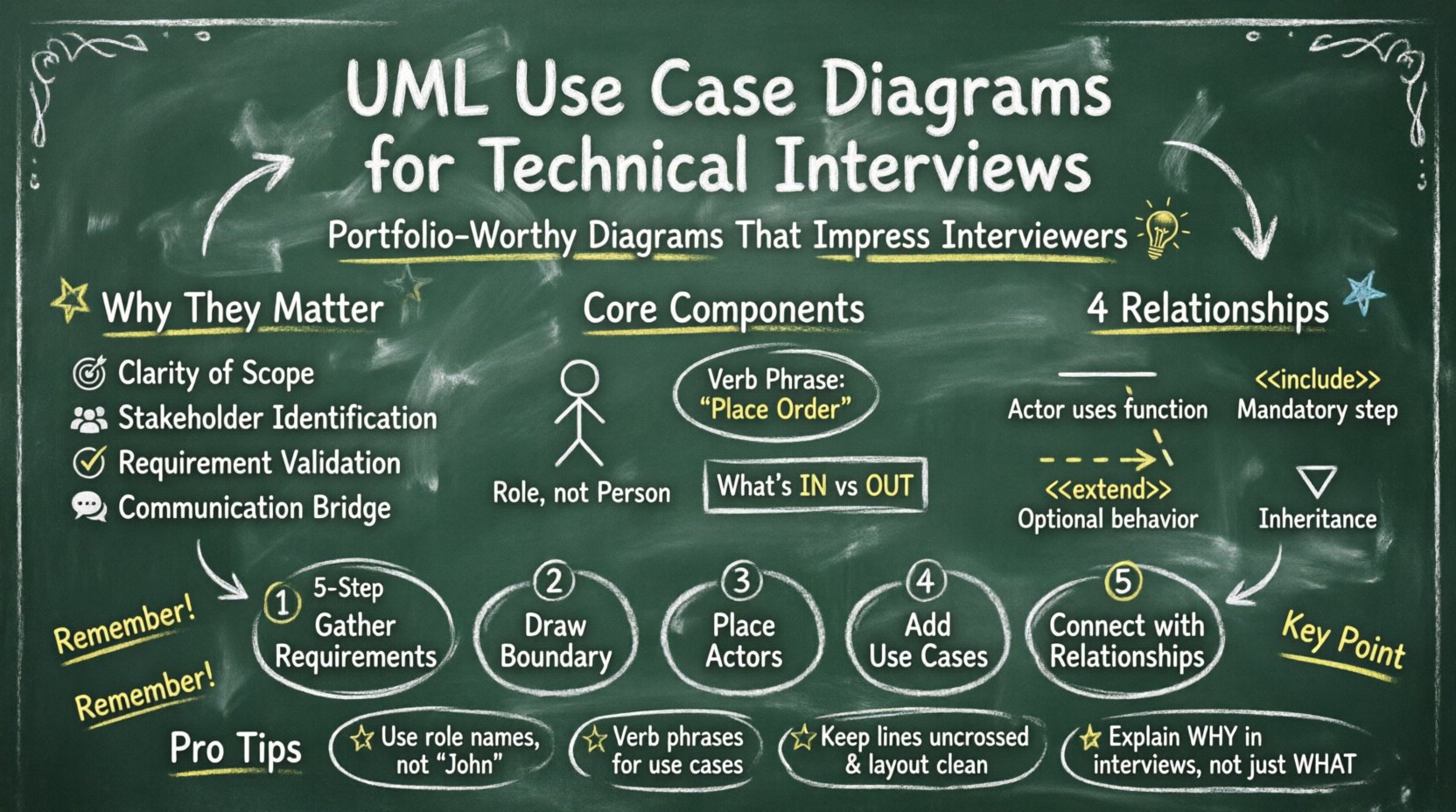
Hiring managers and system architects do not just look for code; they look for architectural thinking. When you present a UML Use Case Diagram, you are signaling that you understand the scope of a project before writing a single line of logic. It shows you can identify the users of a system and what value they derive from it.
Key benefits include:
- Clarity of Scope: It defines what is inside the system and what is outside.
- Stakeholder Identification: It highlights who interacts with the system.
- Requirement Validation: It helps verify that all user goals are met.
- Communication: It serves as a common language between developers, designers, and business analysts.
When preparing for an interview, having a clean, well-annotated diagram ready to discuss can reduce cognitive load for the interviewer. They can focus on your reasoning rather than deciphering messy sketches.
Core Components of a Use Case Diagram 🧩
To build a valid diagram, you must understand the fundamental building blocks. These elements remain consistent regardless of the software used to draw them.
1. Actors 👤
An actor represents a role played by a user or an external system. It is not a specific person, but a category of interaction. Actors are typically depicted as stick figures.
- Primary Actors: Those who initiate the use case to achieve a goal.
- Secondary Actors: Those who support the primary actors or provide data (e.g., a Payment Gateway).
- Internal Actors: Roles existing within the system boundary.
Example: In an online store, the “Customer” is a primary actor. The “Credit Card Processor” is a secondary actor.
2. Use Cases ⚙️
A use case represents a specific functionality or goal the system provides. It is usually an oval shape. The text inside should describe an action, not a feature.
- Focus on Verbs: Use “Place Order” instead of “Ordering Module”.
- Atomic Goals: Each oval should represent one distinct interaction.
- System Boundary: The rectangle containing the use cases defines the system’s limits.
3. System Boundary 📦
This is the rectangle that encloses the use cases. Everything inside belongs to the system; everything outside is an actor or external dependency. Keeping this boundary clear prevents scope creep during discussions.
Understanding Relationships 🕸️
Connecting actors to use cases is where the logic lives. There are four main types of relationships you should know and use correctly.
- Association: A solid line connecting an actor to a use case. It indicates that the actor interacts with that function.
- Include: A dotted arrow labeled <<include>>. It means the base use case always invokes the included use case.
- Extend: A dotted arrow labeled <<extend>>. It means the extending use case adds behavior to the base use case under specific conditions.
- Generalization: A solid line with a hollow triangle. It represents inheritance, where a child actor or use case is a specialized version of the parent.
Using the wrong relationship can confuse the logic flow. Below is a reference table to help you decide which relationship fits your scenario.
| Relationship | Symbol | Meaning | Example |
|---|---|---|---|
| Association | Solid Line | Actor uses the function | Customer → Login |
| Include | Dotted Arrow <<include>> | Mandatory step inside another | Checkout <<include>> Validate Card |
| Extend | Dotted Arrow <<extend>> | Optional step triggered by condition | Login <<extend>> Show Error Message |
| Generalization | Solid Line + Triangle | Inheritance of traits | Admin → User |
Step-by-Step Construction Guide 🛠️
Creating a portfolio-ready diagram requires a methodical approach. Do not start drawing immediately. Follow these phases to ensure accuracy.
Phase 1: Requirement Gathering 📝
Before touching the canvas, list the functional requirements. Ask yourself: What does the system need to do? Who needs to do it?
- Read the project documentation or problem statement carefully.
- Identify the goals of every user type.
- Write down the triggers that start a process.
Phase 2: Define the System Boundary 🚧
Determine what is in scope. If you are designing a “User Management System,” the boundary includes authentication and profile updates. It excludes the actual database server hardware, which is an infrastructure detail.
- Draw a large rectangle.
- Label it with the System Name.
- Ensure all actors are outside this box.
Phase 3: Identify Actors 🧑💼
Place stick figures outside the system boundary. Name them clearly.
- Avoid naming them after specific people (e.g., “John”).
- Use roles (e.g., “Registered User”, “Guest”, “Administrator”).
- Group similar actors using generalization if applicable (e.g., “Staff” generalizes “Manager” and “Employee”).
Phase 4: Define Use Cases 🎯
Place ovals inside the system boundary. Name them with a verb phrase.
- Bad: “Login Screen”
- Good: “Authenticate User”
Keep the number of use cases manageable. A diagram with 50 ovals is unreadable. If you have many, consider splitting the diagram into subsystems.
Phase 5: Connect the Dots 🔗
Draw lines between actors and use cases. Ensure you are using the correct relationship type.
- Does the actor perform the action? Use Association.
- Is there a common step shared by multiple functions? Use Include.
- Is there an optional behavior based on a condition? Use Extend.
Refining for Portfolio Quality ✨
A diagram that works for a sketch is not the same as one for a portfolio. Professional standards require precision and cleanliness.
Consistency in Naming 🏷️
Ensure terminology is consistent throughout the document. If you use “Login” in one place, do not use “Sign In” elsewhere. This reduces confusion for the reader.
Annotation and Notes 📌
Complex logic often needs explanation. Use note symbols to add constraints or detailed rules without cluttering the main flow.
- Use notes for pre-conditions (e.g., “User must be logged in”).
- Use notes for post-conditions (e.g., “Order status updated to ‘Shipped'”).
- Keep notes concise and relevant to the diagram.
Visual Hierarchy 🎨
Even without CSS styling, the layout matters. Arrange use cases logically.
- Group related use cases together.
- Keep lines short to avoid crossing over other elements.
- Place primary actors on the left or top for standard reading flow.
Common Mistakes to Avoid 🚫
Even experienced candidates make errors. Reviewing these pitfalls can save you from losing points during an evaluation.
1. Mixing Levels of Detail
Do not put high-level goals next to low-level database operations. A use case like “Save to Database” is a technical implementation detail, not a user goal. The user cares about “Save Document”, not the SQL query.
2. Overusing Include/Extend
These relationships can make a diagram look messy if overused. Prefer simplifying the diagram by flattening the logic if it becomes too complex. Only use them when they add significant value to understanding the flow.
3. Ambiguous Actors
Ensure actors are distinct. If you have “User” and “Admin”, consider if “Admin” is just a specialized “User”. If so, use generalization. If they have completely different workflows, keep them separate.
4. Ignoring Non-Functional Requirements
While use cases focus on functionality, mention security or performance constraints in your notes. For example, note that “Authentication” requires “2-Factor Verification”.
Interview Presentation Strategy 🗣️
Having the diagram is only half the battle. How you talk about it matters.
- Start with the Goal: “I designed this to clarify the interaction between the customer and the payment system.”
- Walk Through the Flow: “First, the Guest Actor accesses the system. If they wish to buy, they must Authenticate.”
- Highlight Decisions: “I chose to use an Include relationship here because the validation step is mandatory for both Checkout and Express Buy.”
- Invite Feedback: “I considered adding a review feature here, but decided it was out of scope for this iteration.”
This approach shows confidence and a clear understanding of the design choices.
Scenario Walkthrough: E-Commerce System 🛒
Let’s apply these concepts to a practical example. Imagine a simplified online shopping platform.
Actors Identified
- Customer: Browses items and places orders.
- Guest: Browses items but cannot buy.
- Administrator: Manages products and users.
Use Cases Identified
- View Products: Available to both Customer and Guest.
- Add to Cart: Available to Customer.
- Checkout: Available to Customer.
- Manage Inventory: Available to Administrator.
Relationships Defined
- Association: Customer → Checkout.
- Generalization: Customer extends Guest (Customer is a logged-in Guest).
- Include: Checkout → Process Payment.
By structuring it this way, the diagram clearly shows that anyone can browse, but only logged-in users can buy. The payment step is a mandatory part of checkout. This clarity is what interviewers look for.
Final Checklist for Success ✅
Before submitting your diagram or walking into the interview room, run through this list.
- Is the system boundary clearly labeled?
- Are all actor names role-based, not person-based?
- Are use case names verb phrases?
- Are all lines connected correctly (no loose ends)?
- Is the relationship type accurate (Include vs Extend)?
- Is the layout clean and readable without crossing lines?
- Are notes used only for necessary constraints?
- Does the diagram fit on a standard screen or page?
Summary of Best Practices 📋
Creating a UML Use Case Diagram is about communication. It translates business needs into technical structure. By following the steps outlined above, you ensure your work is robust, readable, and professional.
Focus on the actors and their goals. Keep the system boundary strict. Choose relationships deliberately. Review your work for consistency. When you present this in an interview, explain the why, not just the what.
This methodical approach demonstrates that you are not just a coder, but a system thinker. That distinction is often the key to securing the role you want. Good luck with your portfolio and your interviews.