
Modern software systems often begin as prototypes and evolve into complex architectures over years. While this longevity is valuable, it frequently introduces technical debt and obscure logic. Developers face the daunting task of modifying code without breaking existing functionality. This is where UML reverse engineering becomes essential. By visualizing the existing structure, teams can navigate complexity with clarity.
Refactoring is not merely about rewriting code; it is about understanding the intent behind it. Unified Modeling Language (UML) provides the visual grammar needed to decode legacy systems. This guide outlines a structured approach to applying UML techniques to improve maintainability and reduce risk.
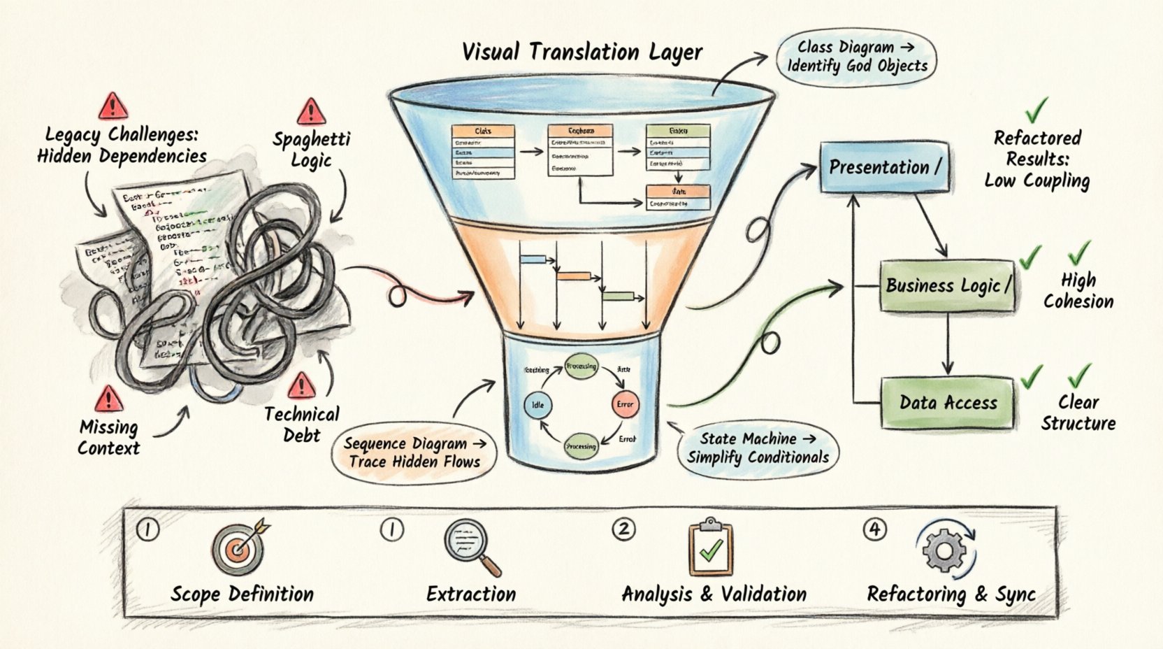
🧩 Understanding the Legacy Challenge
Legacy code presents unique obstacles. It often lacks documentation, relies on implicit knowledge, and contains tight coupling. Attempting to refactor without a map leads to regression bugs and instability.
- Hidden Dependencies: Modules interact in ways not immediately obvious from the source code alone.
- Spaghetti Logic: Control flow may be nested deeply, making branching paths difficult to trace.
- Inconsistent Standards: Coding conventions may have shifted over time, creating visual noise.
- Missing Context: Original architects may have left the project, leaving business rules undocumented.
Reverse engineering addresses these issues by creating a visual abstraction layer. It translates code back into a design representation, allowing engineers to see the system as a whole rather than a collection of files.
📐 The Role of UML in Reverse Engineering
UML is a standardized modeling language used to specify, construct, and document the artifacts of software systems. In the context of legacy refactoring, it serves as a translation tool.
When working with an existing codebase, the goal is to extract architectural information. The process involves:
- Scanning the code structure.
- Identifying classes, interfaces, and their relationships.
- Mapping runtime behaviors to static structures.
- Creating a blueprint that represents the current state.
This blueprint acts as a baseline. Before making changes, engineers can verify that the refactored code matches the original intent depicted in the model.
🔄 The Reverse Engineering Workflow
Executing a reverse engineering project requires a disciplined workflow. Rushing into code changes without a model is a common cause of failure. Follow these steps to ensure accuracy.
1. Preparation and Scope Definition
Define the boundaries of the refactoring effort. A monolithic application may need to be split into manageable modules. Selecting the right scope prevents scope creep.
- Identify critical paths that impact business logic.
- Pinpoint areas with high defect rates.
- Isolate components with high coupling.
2. Extraction of Structural Information
Use modeling tools to parse the source code. This process generates initial diagrams automatically. The output provides a starting point for manual refinement.
- Extract class definitions, attributes, and methods.
- Map inheritance hierarchies and interface implementations.
- Identify association, aggregation, and composition relationships.
3. Analysis and Validation
Automated extraction often misses behavioral nuances. Manual review is necessary to validate the diagrams against the actual code execution.
- Check for orphaned classes or unused dependencies.
- Verify that relationships accurately reflect data flow.
- Ensure that access modifiers (public, private) are correctly represented.
4. Refactoring and Synchronization
Once the model is accurate, begin the refactoring process. Changes should be made in small iterations, synchronizing the code and the model frequently.
- Apply design patterns to improve structure.
- Remove code smells such as duplicated logic.
- Update the UML diagrams to reflect the new state.
📊 Generating Specific Diagrams for Legacy Analysis
Different UML diagram types serve different purposes. For legacy refactoring, a combination of structural and behavioral diagrams is required. Each diagram type highlights specific aspects of the system.
| Diagram Type | Primary Use Case | Legacy Benefit |
|---|---|---|
| Class Diagram | Visualize structure and relationships | Identifies tight coupling and complex inheritance |
| Sequence Diagram | Model object interactions over time | Traces hidden logic flows and API calls |
| State Machine Diagram | Represent object lifecycle states | Clarifies complex conditional logic |
| Component Diagram | Show high-level system organization | Maps module dependencies and boundaries |
| Deployment Diagram | Illustrate hardware and software topology | Understands environment-specific constraints |
Class Diagrams: The Foundation
Class diagrams are the most common starting point. They show the static structure of the system. In legacy code, these diagrams often reveal God Objects or Long Methods.
- High Cohesion: Ensure classes have a single responsibility.
- Low Coupling: Reduce dependencies between unrelated modules.
- Inheritance Depth: Flatten deep hierarchies to improve readability.
Sequence Diagrams: Tracing Behavior
Static structure does not always explain dynamic behavior. Sequence diagrams capture the flow of messages between objects. This is crucial for understanding legacy business logic.
- Trace the path of a user request through the system.
- Identify circular dependencies that cause stack overflow risks.
- Visualize error handling paths that are often overlooked.
State Machine Diagrams: Managing Logic
Legacy systems often use complex if-else or switch statements to manage state. State machine diagrams replace this with a clear visual representation of states and transitions.
- Convert nested conditionals into state transitions.
- Identify unreachable states that can be removed.
- Clarify event handling mechanisms.
🛠️ Refactoring Strategies Based on Diagrams
Once the UML models are established, specific refactoring strategies can be applied. The diagrams act as a guide for where changes are safe and where they are risky.
1. Breaking Down Large Classes
If a class diagram reveals a class with excessive methods, apply the Extract Class pattern. Split responsibilities into smaller, focused classes.
- Move related attributes to a new class.
- Preserve the original interface to minimize impact.
- Update the class diagram to show the new relationship.
2. Reducing Coupling
High coupling is visible in the association lines of a class diagram. Reduce these connections by introducing interfaces or dependency injection.
- Replace concrete implementations with interfaces.
- Use dependency injection containers to manage lifecycles.
- Introduce facade patterns to simplify complex subsystems.
3. Simplifying Inheritance
Deep inheritance trees are hard to maintain. The class diagram helps visualize the hierarchy. Consider replacing inheritance with composition.
- Move shared logic to a utility class or mixin.
- Use delegation to forward behavior.
- Ensure polymorphism is still supported where needed.
4. Aligning Code with Design
Often, the code drifts away from the intended design. The UML model serves as the target state. Refactor the code to match the model, or update the model if the code represents a valid evolution.
- Document the rationale for deviations.
- Ensure the updated model is committed to the repository.
- Keep the model and code in sync via automated tools.
🧪 Validation and Testing
Refactoring is only successful if the behavior remains unchanged. Validation ensures that the new structure does not introduce regressions.
- Unit Testing: Write tests for critical paths identified in sequence diagrams.
- Integration Testing: Verify that modules interact correctly after changes.
- Regression Testing: Run the full test suite to catch unintended side effects.
- Visual Verification: Compare the new class diagram with the target design.
Automated testing is non-negotiable. Without a safety net, refactoring becomes a guessing game. Ensure coverage is high for the areas being modified.
⚠️ Common Pitfalls to Avoid
Even with a solid plan, errors can occur. Awareness of common mistakes helps mitigate risks.
- Over-Modeling: Creating too many diagrams can slow down progress. Focus on the most complex parts of the system.
- Ignoring Tests: Skipping tests in favor of visual inspection leads to bugs.
- Manual Diagramming: Relying solely on hand-drawn diagrams without code synchronization leads to drift.
- Ignoring Domain Knowledge: Technical structure is useless if it does not reflect business rules. Consult stakeholders.
- One-Time Effort: Treat diagrams as living documents. Update them as the system evolves.
🔗 Integrating with Development Workflow
UML reverse engineering should not be a separate phase. It must be integrated into the daily workflow of the development team.
- Continuous Integration: Run diagram generation as part of the build process.
- Code Reviews: Include diagram updates in pull requests.
- Documentation: Store diagrams alongside code repositories.
- Training: Ensure all team members understand the UML notation used.
This integration ensures that the documentation remains current. It prevents the model from becoming obsolete shortly after creation.
📈 Measuring Success
How do you know the refactoring effort was worthwhile? Metrics provide objective evidence of improvement.
- Cyclomatic Complexity: Look for a reduction in the complexity of methods.
- Coupling Metrics: Measure the number of dependencies per class.
- Defect Rate: Track the frequency of bugs in refactored modules.
- Development Speed: Monitor the time required to implement new features.
A successful refactoring effort results in code that is easier to understand and modify. The UML diagrams serve as the evidence of this structural improvement.
🔚 Summary
Refactoring legacy code is a necessary task for maintaining software health. UML reverse engineering provides the visual tools required to understand complex systems. By following a structured workflow, teams can reduce risk and improve code quality.
The process involves extraction, analysis, and validation. It requires discipline to keep models in sync with code. However, the long-term benefits of maintainability and clarity make the effort worthwhile. Teams that adopt these practices build a foundation for sustainable growth.
Start with the most critical components. Apply the techniques gradually. Document the changes. Over time, the system becomes more resilient and easier to manage.