
Creating a visual representation of system interactions is a critical skill for any software architect or business analyst. A UML Use Case Diagram serves as the blueprint for understanding how users interact with a system. This guide provides a detailed walkthrough on constructing these diagrams accurately without relying on specific commercial tools. We will focus on the fundamental principles, relationships, and best practices required for clear system modeling.
Introduction to Use Case Modeling 📝
A Use Case Diagram captures the functional requirements of a system. It describes what the system does from the perspective of external actors. Unlike sequence diagrams that focus on timing, or class diagrams that focus on data structure, the Use Case Diagram focuses on behavior and interaction.
Why is this important?
- Communication: It bridges the gap between technical teams and stakeholders.
- Scope Definition: It clearly delineates what is inside and outside the system boundary.
- Requirement Gathering: It helps identify missing functionality during the planning phase.
When you start drawing, remember that simplicity is key. A complex diagram confuses readers. Aim for clarity over density. Every element on the page should serve a purpose in defining the system’s scope.
Core Components Explained 🧩
To draw an accurate diagram, you must understand the standard symbols used in Unified Modeling Language (UML). These symbols are standardized to ensure consistency across different projects and teams.
1. Actors 👤
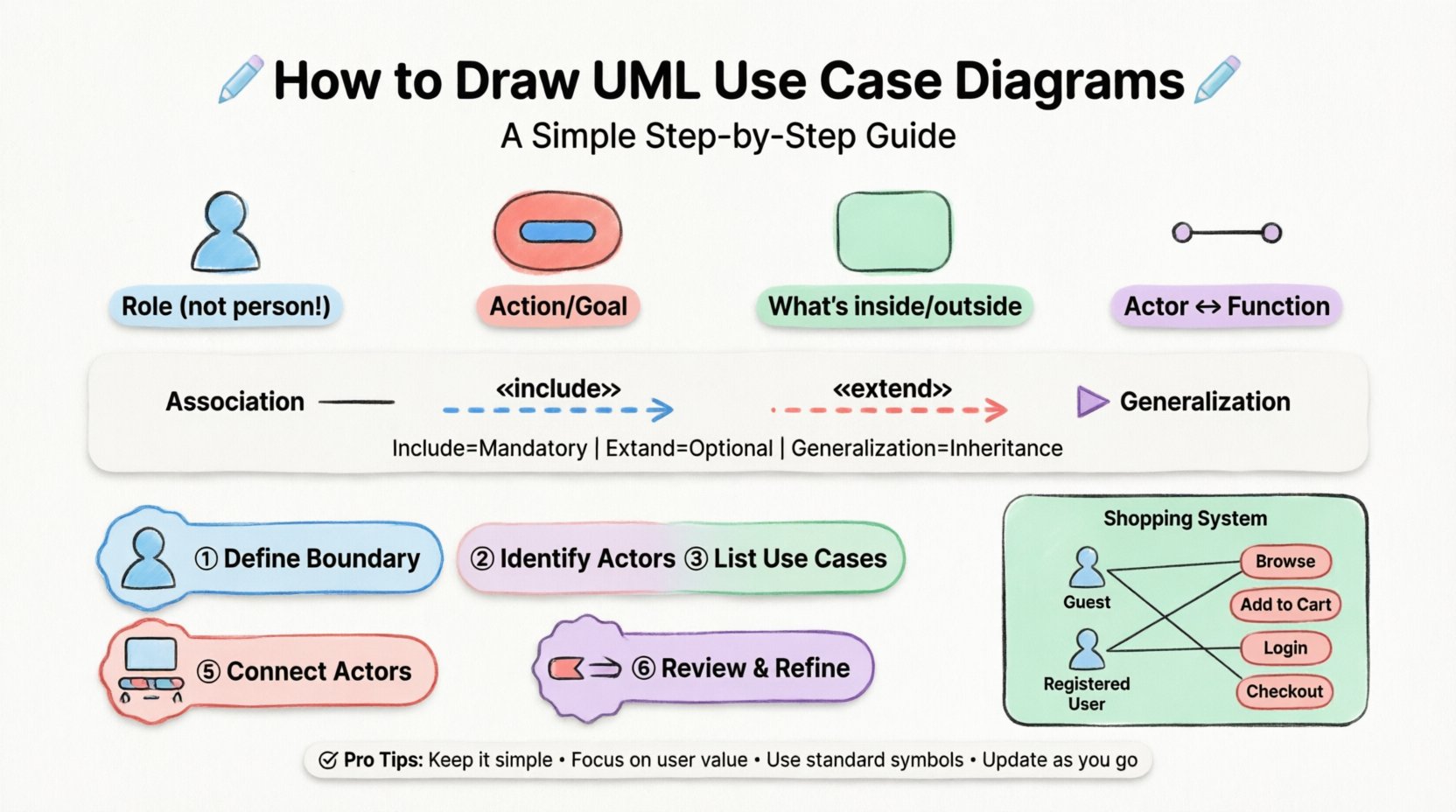
An actor represents a role played by a user or an external system. It is depicted as a stick figure. Importantly, an actor is not a specific person (like “John”); it is a role (like “Administrator” or “Customer”).
- Primary Actors: Those who initiate the use case to achieve a goal.
- Secondary Actors: Those that support the primary actor but do not initiate the process.
2. Use Cases 🔵
A use case represents a specific function or service provided by the system. It is drawn as an oval or ellipse. The text inside should describe an action, such as “Place Order” or “Generate Report”.
3. System Boundary ⬜
The rectangle box represents the system under consideration. Everything inside is part of the system. Everything outside is external. This boundary helps prevent scope creep during development.
4. Associations 📏
The solid line connecting an actor to a use case indicates communication. It shows that the actor interacts with that specific function.
Understanding Relationships 🔄
Relationships define how use cases interact with each other and with actors. There are four primary types of relationships in UML Use Case Diagrams. Understanding the distinction between them is vital for accuracy.
| Relationship Type | Symbol | Meaning | When to Use |
|---|---|---|---|
| Association | Solid Line | Actor interacts with Use Case | Standard interaction flow |
| Include | Dashed Arrow «include» | Mandatory behavior included in another | Reuse of common steps (e.g., Login) |
| Extend | Dashed Arrow «extend» | Optional behavior added to another | Exception handling or optional features |
| Generalization | Solid Line with Hollow Triangle | Inheritance of behavior | Actor or Use Case specialization |
Include Relationship: This is mandatory. If you use Case A, you must also use Case B. For example, “Place Order” includes “Log In”. You cannot place an order without logging in first.
Extend Relationship: This is optional. The base use case works fine on its own, but the extended case adds functionality under specific conditions. For example, “Place Order” might be extended by “Apply Coupon”. The order works without the coupon, but the coupon is an optional addition.
Generalization: This represents inheritance. A specific actor is a type of a general actor. For instance, “Admin” is a generalization of “User”. If a “User” can “View Profile”, the “Admin” can also “View Profile” automatically.
Step-by-Step Process 🛠️
Creating a diagram from scratch requires a structured approach. Follow these steps to ensure your model is logical and complete.
Step 1: Define the System Boundary
Start by drawing a large rectangle. Write the name of the system inside it. This defines the limits of your project. Ask yourself: What is the core function of this software? Everything outside this box is external.
Step 2: Identify the Actors
List all the roles that interact with the system. Do not list specific individuals. Think about roles. Common roles include:
- Customer
- Administrator
- Third-Party System
- Payment Gateway
Place these stick figures outside the system boundary.
Step 3: Identify the Use Cases
Brainstorm the goals each actor wants to achieve. Use verbs and nouns. Examples:
- Register Account
- Search Product
- Process Payment
- Send Notification
Draw ovals inside the system boundary. Group them logically if possible.
Step 4: Connect Actors to Use Cases
Draw solid lines between actors and the use cases they interact with. Ensure every actor has at least one connection. If an actor is not connected to anything, they are not part of the system scope.
Step 5: Define Relationships Between Use Cases
Review your use cases for dependencies. Are there common steps shared across multiple functions? Use include relationships for mandatory steps. Use extend relationships for optional steps. This reduces clutter by avoiding repetitive drawings.
Step 6: Review and Refine
Walk through the diagram as if you were a user. Does the flow make sense? Are there any orphaned actors? Is the system boundary clear? Ask a colleague to review it for clarity.
Practical Example: Online Shopping System 🛒
To illustrate the process, let us walk through a simple Online Shopping System. This example demonstrates how to apply the rules discussed above.
Scenario Analysis
Imagine a platform where users can browse items, add them to a cart, and checkout. There are two main actors: Guest User and Registered User.
Step-by-Step Construction
- Boundary: Draw a box labeled “Online Shopping System”.
- Actors: Add “Guest User” and “Registered User” outside the box.
- Use Cases: Inside the box, add ovals for “Browse Catalog”, “Add to Cart”, “Login”, “Checkout”, “View Order History”.
- Associations:
- Connect “Guest User” to “Browse Catalog” and “Add to Cart”.
- Connect “Registered User” to “Browse Catalog”, “Add to Cart”, “Login”, and “View Order History”.
- Relationships:
- Connect “Login” to “Checkout” using an «include» relationship. This means you cannot checkout without logging in.
- Connect “Add to Cart” to “Checkout”. This is a standard association.
- Create a “Guest Checkout” use case. Connect “Guest User” to it.
In this scenario, “Registered User” is a generalization of “Guest User”. They share common behaviors like browsing, but the Registered User has additional privileges like viewing history.
Common Pitfalls to Avoid ⚠️
Even experienced modelers make mistakes. Being aware of common errors helps you maintain high quality.
1. Over-Complicating the Diagram
Do not draw every single button click as a use case. Use cases should represent value to the user, not technical implementation details. “Click Button” is not a use case. “Submit Form” is.
2. Ignoring the System Boundary
If you place a use case outside the box, it implies the system does not handle it. If you place an actor inside, it implies the system is the actor. Keep the boundary strict.
3. Misusing Include and Extend
A common error is using include for optional steps. If a step is optional, use extend. If it is mandatory, use include. Confusing these changes the logic of the requirement.
4. Missing Actors
Do not forget external systems. If your software sends data to a database or a payment processor, those are actors (or secondary actors) that must be represented.
5. Labeling Actors as People
Never label an actor “John Smith”. Label them “Customer”. Roles change, people leave, but the role remains constant in the system design.
Integration with Use Case Specifications 📄
A diagram is a high-level view. It does not contain the detailed logic. For a complete model, you should pair the diagram with Use Case Specifications (or Descriptions).
Each oval in your diagram corresponds to a text document that details:
- Preconditions: What must be true before the use case starts?
- Postconditions: What must be true after it finishes?
- Main Flow: The step-by-step interaction between actor and system.
- Alternative Flows: What happens if things go wrong?
The diagram acts as the map, and the specifications act as the detailed instructions. Without the specifications, the diagram is incomplete.
Maintenance and Iteration 🔄
Software requirements change. Your diagrams must evolve to reflect reality.
- Version Control: Keep track of changes. If a use case is removed, update the diagram immediately.
- Stakeholder Feedback: Regularly show the diagram to business stakeholders. They may identify new actors or missing functions.
- Consistency Checks: Ensure that the diagram matches the code. If a feature is implemented but not on the diagram, update the diagram.
Conclusion on Best Practices ✅
Building accurate UML Use Case Diagrams requires discipline and a clear understanding of system boundaries. By focusing on roles rather than individuals, and behaviors rather than implementation details, you create a model that is both robust and understandable.
Remember these core principles:
- Keep the system boundary clear.
- Use standard symbols consistently.
- Distinguish between mandatory and optional interactions.
- Focus on user value.
With practice, creating these diagrams becomes an intuitive part of the design process. They serve as a foundational document that guides the entire development lifecycle, ensuring that the final product meets the needs of its users.