
System modeling requires precision, clarity, and a shared understanding among stakeholders. Among the various diagram types available in the Unified Modeling Language (UML), the Communication Diagram offers a unique perspective on object interactions. Unlike other structural or behavioral diagrams, this format emphasizes the structural organization of objects while simultaneously depicting their interactions. This guide outlines the essential standards for creating effective diagrams that enhance documentation and system comprehension.
Understanding the Communication Diagram Context 🧩
A Communication Diagram, formerly known as a Collaboration Diagram, focuses on the flow of messages between objects. It represents the structural relationships between objects as a network of nodes and links. While Sequence Diagrams highlight the time-based ordering of messages, Communication Diagrams prioritize the spatial arrangement and connectivity of system components. This makes them particularly useful for understanding complex interactions within a specific subsystem.
When drafting these diagrams, the goal is to reduce cognitive load for the reader. A well-constructed diagram allows a developer to trace the path of data without confusion. It serves as a blueprint for implementation and a reference for debugging. To achieve this, one must adhere to specific modeling standards that ensure consistency and readability across the entire project documentation.
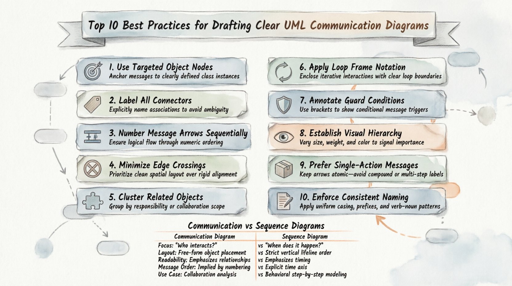
1. Define Objects with Precision 🎯
The foundation of any effective diagram lies in the clarity of its constituent parts. Objects represent instances of classes within the system. Each object box must be labeled with its specific class name and, if necessary, an instance name.
- Instance Naming: Use the format instanceName : ClassName. This distinguishes multiple instances of the same class.
- Role Identification: Indicate the role an object plays in the interaction if it differs from its class definition.
- Scope Limitation: Do not include objects that do not participate in the specific interaction being modeled. Keep the scope relevant to the scenario.
Ambiguous labels lead to misunderstandings during the development phase. If an object represents a database connection, label it clearly as dbConnection : DatabaseConnector. Avoid generic labels like Object1 or Entity. Specificity aids in mapping the diagram directly to code structures.
2. Label Links with Context 🏷️
Links represent the structural relationships between objects. In a Communication Diagram, links are the channels through which messages travel. Each link must be clearly labeled to indicate the relationship type.
- Association Labels: Use standard UML association names (e.g., owns, manages) to define how objects relate.
- Navigation Direction: Indicate if the relationship is navigable in both directions or just one.
- Multiplicity: Where applicable, specify the number of instances connected (e.g., 1, 0..1, *).
Clear link labels help developers understand the underlying architecture. If a link connects a User object to a Session object, the label should reflect the nature of that connection, such as creates or manages. This provides context that goes beyond simple connectivity.
3. Number Messages Sequentially 🔢
One of the distinct features of a Communication Diagram is the use of sequence numbers on messages. These numbers establish the order of execution, even though the diagram does not explicitly plot time on a vertical axis.
- Start at 1: Begin the sequence with the number 1 for the initiating message.
- Incremental Ordering: Use integers (1, 2, 3) to denote the chronological flow.
- Nested Calls: Use decimal notation for nested calls (e.g., 1.1, 1.2) to show that a message is sent in response to a previous message.
This numbering system is critical for understanding the control flow. Without it, the diagram becomes a static map of connections rather than a dynamic representation of behavior. Ensure that the sequence numbers are visible and legible on every message link.
4. Minimize Link Crossing 🚫
Visual clutter is the enemy of comprehension. When link lines cross each other excessively, it becomes difficult to trace the path of a specific message. Layout management is a key skill in drafting these diagrams.
- Cluster Related Objects: Group objects that interact frequently close to one another.
- Route Links Carefully: Use orthogonal routing (horizontal and vertical lines) rather than diagonal lines where possible.
- Adjust Node Positions: Move objects to eliminate intersections without breaking the logical structure.
A clean layout reduces the time required to read the diagram. If three lines intersect at a single point, it suggests a potential design complexity that may need simplification. Aim for a layout where the path of every message is distinct and traceable.
5. Group Related Interactions 🧩
Complex systems often involve multiple scenarios. Instead of creating a single, massive diagram, consider grouping interactions by functional area or use case. This approach keeps individual diagrams focused and manageable.
- Scenario-Based: Create separate diagrams for distinct user stories or use cases.
- Subsystem Grouping: If modeling a large system, divide the diagram by subsystem boundaries.
- Logical Clusters: Use visual spacing or containers to indicate logical groupings of objects.
Fragmenting the information allows stakeholders to focus on one aspect of the system at a time. A single diagram containing fifty objects and fifty messages is rarely useful. Breaking it down into smaller, logical units improves maintainability and clarity.
6. Represent Loops Clearly 🔄
Real-world systems often involve iterative processes. A Communication Diagram must accurately represent loops without creating visual confusion. The standard UML notation for loops uses a combined fragment or explicit message repetition.
- Loop Notation: Use the standard loop frame to enclose the repeated interaction.
- Iteration Count: Specify the condition for the loop (e.g., while (hasMoreItems)).
- Message Repetition: If the same message is sent multiple times, indicate this with the sequence number prefix (e.g., 1.1, 1.2, 1.3).
Clarity in loops prevents misinterpretation of the algorithm. Developers need to know exactly when the iteration starts and stops. Explicit notation ensures that the logic is preserved when the design is translated into code.
7. Use Guard Conditions Wisely 🛡️
Guard conditions define the logic that determines if a message is sent. They are typically placed on the message link or within a decision node. Overusing guards can clutter the diagram.
- Placement: Place guard conditions directly on the arrow or near the message label.
- Simplicity: Keep conditions short and readable. Avoid complex boolean logic in the diagram.
- Necessity: Only include guards that are critical to the interaction flow. Minor checks can be documented in text.
Effective use of guard conditions highlights the decision points in the system. It informs the developer where the flow might diverge. However, excessive branching makes the diagram difficult to follow. Balance detail with readability.
8. Maintain Visual Hierarchy 👁️
Visual hierarchy helps the reader identify the most important elements first. Size, color, and placement all contribute to this hierarchy.
- Key Actors: Highlight the initiating object or the primary actor in the interaction.
- Object Size: Ensure object boxes are of consistent size to avoid implying importance based on dimensions.
- Message Weight: Use line thickness or bold text to emphasize critical messages if necessary.
A consistent visual style across all diagrams in a project aids in quick recognition. If every diagram follows the same layout rules, the team can read new diagrams faster. Consistency is a form of quality control in documentation.
9. Avoid Message Overload 📦
A single message should convey one specific action. Packing multiple actions into one label creates ambiguity.
- Single Action: Each arrow should represent one method call or data transfer.
- Parameter Clarity: List parameters clearly, but avoid long strings of text.
- Return Values: Indicate return messages distinctly, often with a dashed line.
Overloaded messages confuse the reader about the exact sequence of events. If a message requires complex parameter passing, document it separately or use a simpler label in the diagram. The diagram is a high-level view, not a code specification.
10. Ensure Naming Consistency 📝
Naming conventions are the backbone of maintainable documentation. Inconsistent naming across diagrams makes cross-referencing difficult.
- Class Names: Use PascalCase for classes (e.g., CustomerOrder).
- Method Names: Use camelCase for methods (e.g., processPayment).
- Object Names: Use lowercase with underscores for instances (e.g., order_instance).
Adhering to a strict naming standard ensures that the diagram maps cleanly to the source code. It reduces the friction between the design phase and the implementation phase. Review naming conventions regularly to ensure compliance.
Communication vs. Sequence Diagrams: A Comparison 📊
Understanding when to use a Communication Diagram versus a Sequence Diagram is vital for effective modeling. Both depict interactions, but they emphasize different aspects of the system.
| Feature | Communication Diagram | Sequence Diagram |
|---|---|---|
| Focus | Structural organization of objects | Time-based ordering of messages |
| Layout | Network of nodes and links | Vertical time axis |
| Readability | Better for complex connections | Better for long sequences |
| Message Order | Indicated by sequence numbers | Indicated by vertical position |
| Use Case | High-level interaction overview | Detailed step-by-step logic |
Choose the diagram type based on the information you need to convey. If the structural relationship is more important than the timing, use the Communication Diagram. If the sequence of events is the primary concern, the Sequence Diagram is the better choice.
Maintenance and Versioning 🔄
Diagrams are living documents. They must evolve alongside the software. Regular maintenance ensures that the documentation remains accurate.
- Review Cycles: Schedule periodic reviews of diagrams during sprint planning.
- Change Tracking: Update diagram versions when significant architectural changes occur.
- Feedback Loop: Encourage developers to report discrepancies between the diagram and the code.
Outdated diagrams create technical debt. They mislead new team members and complicate debugging. Treat the diagram as a critical part of the codebase that requires the same care and version control as the source files.
Common Pitfalls to Avoid ⚠️
Even experienced modelers can fall into common traps. Being aware of these pitfalls helps in producing higher quality work.
- Ignoring Multiplicity: Failing to specify how many objects can interact leads to implementation errors.
- Overcomplicating: Trying to show every possible edge case in one diagram reduces clarity.
- Inconsistent Notation: Mixing different UML notations can confuse the reader.
- Lack of Context: Providing a diagram without explaining the scenario it represents.
By avoiding these issues, you ensure that the diagrams serve their intended purpose. They become tools for communication rather than obstacles. Focus on the core interactions that define the system’s behavior.
Final Thoughts on Diagram Quality 🏁
Clear documentation is a hallmark of professional engineering. The effort spent on refining Communication Diagrams pays dividends in reduced misunderstandings and smoother development cycles. Adhering to these best practices creates a standard of quality that benefits the entire team.
Remember that the goal is communication, not just compliance with a standard. If a diagram is easy to understand, it is a good diagram. Use the guidelines provided here to enhance clarity, maintain consistency, and support the development process effectively. Continuous improvement in modeling skills leads to better system architecture and more robust software solutions.