
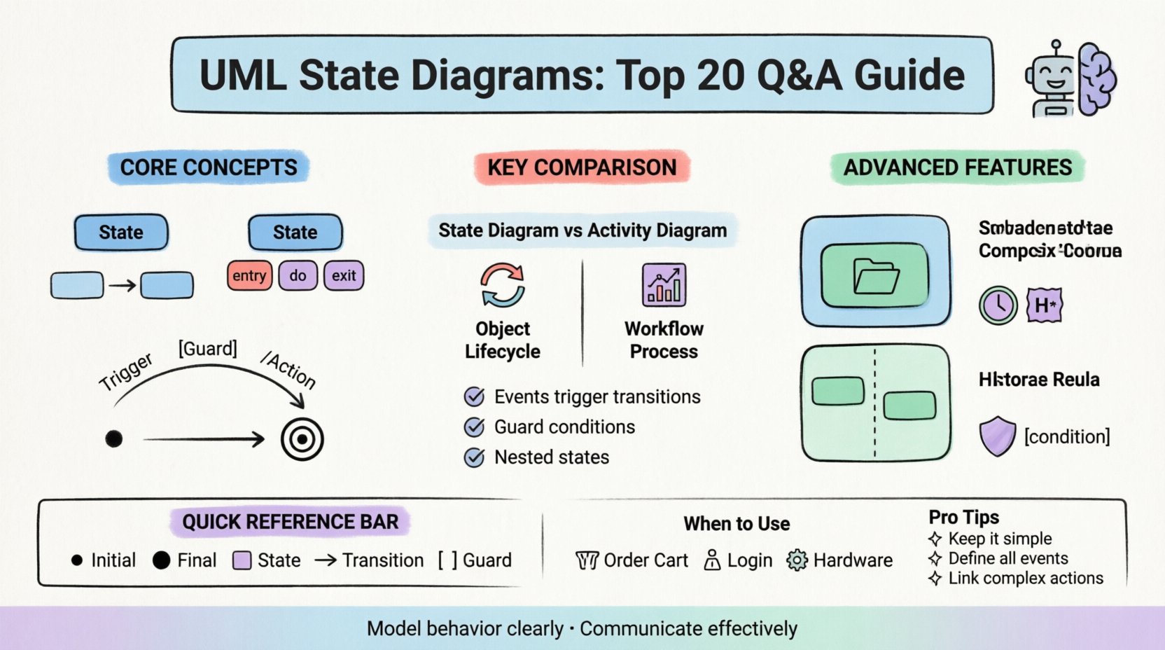
Understanding how a system behaves over time is critical for robust software architecture. While class diagrams describe structure, UML State Diagrams (also known as State Machine Diagrams) describe the dynamic behavior of individual objects. This guide addresses common inquiries regarding the design, syntax, and application of state models.
Whether you are documenting a login workflow or modeling a complex embedded system controller, clarity is paramount. We will explore twenty specific questions that often arise during the modeling process.
Foundational Concepts
1. What exactly is a UML State Diagram? 🖼️
A UML State Diagram is a behavioral diagram that illustrates the different states an object can be in during its lifecycle. It maps out how the object responds to specific events. Unlike a flowchart, which shows a linear process, a state diagram shows branching paths based on conditions and history.
- It focuses on the object’s life cycle.
- It highlights state transitions.
- It defines actions associated with entering, exiting, or being in a state.
2. How does it differ from an Activity Diagram? 🔄
Both diagrams model behavior, but they serve different purposes. An Activity Diagram resembles a flowchart and focuses on the flow of control or data from activity to activity. A State Diagram focuses on the life cycle of a single object and the events that trigger changes.
| Feature | Activity Diagram | State Diagram |
|---|---|---|
| Focus | Workflow / Process | Object Lifecycle |
| Granularity | High-level processes | Individual object states |
| Events | Triggers flow | Triggers transitions |
| Concurrent | Parallel flows possible | Fork/Join nodes common |
3. What is a State? 🟦
A state represents a condition or situation during the life of an object where it satisfies some condition, performs some activity, or waits for some event. States are typically represented by rounded rectangles.
- Simple State: No internal structure.
- Composite State: Contains sub-states (nested states).
- Final State: Represents the termination of the lifecycle.
4. What is a Transition? ⬅️➡️
A transition is the mechanism that moves the system from one state to another. It is triggered by an event. A transition can have a guard condition attached. If the condition evaluates to true, the transition occurs.
- Source state: The state where the transition begins.
- Target state: The state where the transition ends.
- Trigger: The event that initiates the move.
- Guard: A boolean expression that must be true.
- Action: The activity performed during the transition.
5. What is the Initial State? ⚫
The initial state indicates the starting point of the system or object. It is represented by a solid black circle. Every state machine must have exactly one initial state. It is not an action, but a marker indicating where the process begins.
Advanced Syntax and Mechanics
6. How do Guard Conditions work? 🛡️
Guard conditions restrict when a transition can occur. They are written in square brackets, like [condition]. If multiple transitions leave the same state, the system evaluates the guards. Only one path is typically taken based on which condition is met.
- Ensure guards are mutually exclusive if possible.
- Use clear boolean logic.
- Avoid complex logic that obscures the diagram’s readability.
7. What are Entry, Exit, and Do Actions? 🛠️
These actions define what happens when interacting with a state.
- Entry (/entry): Executed when the state is entered.
- Exit (/exit): Executed when the state is left.
- Do (/do): Executed while the object remains in the state. Useful for continuous monitoring or long-running tasks.
8. What is a Composite State? 📦
A composite state is a state that contains other states. This allows for hierarchical modeling. It reduces clutter by grouping related sub-states together. It implies that when the composite state is active, one of its sub-states must be active.
9. What is a History State? 📜
A history state allows a system to remember which sub-state it was in before exiting a composite state. There are two types:
- Deep History: Remembers the specific sub-state deep within the hierarchy.
- Shallow History: Remembers the last active sub-state of the composite state directly.
10. How are Orthogonal Regions used? ⬇️⬆️
Orthogonal regions allow a composite state to have multiple independent sub-states active simultaneously. This is represented by a dashed line dividing the state. This models concurrency, where different aspects of the object change state independently.
Modeling Logic and Patterns
11. What is the difference between a State and a Class? 🏗️
A Class Diagram defines the static structure and attributes of a system. A State Diagram defines the dynamic behavior of a specific instance. You might have a class User, and the State Diagram for that class defines how a user moves from LoggedOut to Active to Blocked.
12. Can a state have multiple outgoing transitions? 🛣️
Yes. However, to prevent ambiguity, guards must ensure only one path is valid at a time. If no guard is present, the transition is always available, which can lead to non-deterministic behavior if multiple exist.
13. What happens if no event triggers a transition? ⏸️
If the object is in a state and no relevant event occurs, it remains in that state indefinitely. This is known as an idle state. The system waits for input or an internal timer.
14. How do you handle invalid states? ❌
Invalid states are often handled via transitions to an error state or a wait-for-recovery state. It is crucial to define where the object goes if it receives an unexpected event while in a specific state.
- Define a default error state.
- Log the invalid transition for debugging.
- Ensure recovery paths exist.
15. What is a Trigger? 📢
A trigger is the event that initiates a transition. Triggers can be:
- Signal events (asynchronous).
- Call events (synchronous).
- Time events (timers).
- Change events (when a condition becomes true).
Implementation and Best Practices
16. When should you use a State Diagram? 📅
Use them when the behavior of an object depends heavily on its current state. Examples include:
- Order processing systems.
- Network protocols.
- User authentication flows.
- Hardware control systems.
Do not use them for simple linear processes where a flowchart suffices.
17. What are common modeling mistakes? 🚫
Common errors include:
- Creating too many states, making the diagram unreadable.
- Forgetting to define the initial state.
- Not defining transitions for all possible events.
- Using state diagrams for complex algorithms rather than state management.
18. How do you document actions in the diagram? 📝
Actions should be described succinctly using pseudo-code or natural language. If the action is complex, consider linking to a detailed specification document rather than cluttering the diagram.
19. Does this impact system performance? ⚙️
The diagram itself is documentation. However, the logic it represents affects performance. Complex state machines with deep nesting or high concurrency can impact runtime efficiency if not implemented carefully in code.
20. How do you integrate this with code? 💻
State diagrams often map directly to design patterns like the State Pattern. Each state becomes a class or a case in a switch statement. The transitions become method calls or logic branches. Keeping the diagram updated is vital for maintaining the codebase.
Summary of State Elements
| Element | Symbol | Description |
|---|---|---|
| Initial State | ● | Start point of the lifecycle |
| Final State | ⬤ | End point of the lifecycle |
| State | ⬜ | A condition or situation |
| Transition | ➡️ | Move from one state to another |
| Event | Label on arrow | Trigger for a transition |
| Guard | [Condition] | Condition for transition to occur |
Final Thoughts on Behavioral Modeling 🧠
Creating a clear model requires discipline. A well-drawn state diagram serves as a contract between designers and developers. It ensures that everyone understands how the system reacts under pressure or unexpected inputs.
By addressing these twenty questions, you establish a foundation for accurate modeling. Focus on clarity over complexity. If a diagram becomes too crowded, consider breaking it into sub-diagrams. This approach maintains readability and ensures the documentation remains a useful tool throughout the project lifecycle.
Remember, the goal is communication. Whether for stakeholders or future maintainers, the diagram must tell the story of the object’s behavior without ambiguity.