
In the landscape of software development, the gap between business requirements and technical implementation often leads to costly rework. One of the most effective tools to bridge this divide is the UML Use Case Diagram. It serves as a visual contract between stakeholders and developers, defining what the system should do from the perspective of the user. This guide details a real-world scenario where we translate vague business needs into a precise, valid model.
Many teams struggle with the abstraction layer. They jump straight to drawing boxes and lines without understanding the underlying business logic. This results in diagrams that are technically correct but practically useless. We will walk through a specific project involving an online inventory management system. By following this process, you can ensure your diagrams are accurate, actionable, and aligned with actual business goals.
🔍 The Business Scenario: Inventory Management System
To understand the translation process, we must first establish the context. Imagine a mid-sized logistics company, “LogiCorp,” which needs a new internal system to manage warehouse stock. The business stakeholders provided a list of desired features, but they were often vague.
- “We need to track where items are.”
- “Users should be able to order stock.”
- “The system must prevent overselling.”
- “Managers need reports on low stock.”
These statements are business needs, not system functions. Our goal is to convert these into Use Cases. The diagram will serve as the foundation for the system architecture.
🧱 Step 1: Identifying the Actors
The first critical step is determining who interacts with the system. In UML, an Actor represents a role played by a human or an external system. We must avoid confusing specific job titles with roles. For example, “John” is a person, but “Warehouse Manager” is a role.
Primary vs. Secondary Actors
We categorize actors based on their primary interaction with the system:
- Primary Actors: Those who initiate a goal. They start the process.
- Secondary Actors: Those who support the primary actor. They provide data or services but do not start the main flow.
| Actor | Role Description | Primary Goal |
|---|---|---|
| Warehouse Associate | Staff member physically handling goods | Receive and ship physical inventory |
| Inventory Manager | Staff member supervising stock levels | Monitor and adjust stock levels |
| Accounting System | External software application | Record financial transactions |
Notice how we included the “Accounting System” as an actor. This is crucial. It is an external system that the new tool must communicate with. This defines a boundary for the system interaction.
📝 Step 2: Extracting Use Cases from Needs
Once actors are defined, we map the business needs to specific actions. A Use Case represents a complete unit of functionality that provides value to an actor. It is an interaction, not a screen or a screen flow.
Refining the Requirements
Let’s take the vague need: “Users should be able to order stock.” This is too broad. We need to break it down:
- Initiate Order: Starting the request process.
- Select Item: Choosing specific inventory.
- Confirm Order: Finalizing the request.
In the UML model, these might be separate Use Cases or grouped under a larger parent. For clarity, we treat “Place Stock Order” as a single Use Case initiated by the Warehouse Associate.
Validating the Use Case List
Before drawing, review the list against the business needs:
- Does every Use Case have at least one Actor?
- Does every Actor have a goal?
- Are the Use Cases atomic (one single goal)?
If a Use Case has too many steps, it might be a process flow rather than a Use Case. Keep the scope focused on the “what,” not the “how.”
🔗 Step 3: Defining Relationships
A diagram is just a collection of boxes without relationships. The lines between Actors and Use Cases, and between Use Cases themselves, define the logic. We focus on three main relationship types.
Association
This is the standard line connecting an Actor to a Use Case. It implies that the actor participates in that functionality.
- Direction: Usually bidirectional, but implies the Actor initiates or uses the Use Case.
Include
The Include relationship indicates that one Use Case must incorporate the behavior of another. It is mandatory.
- Example: “Login” is a common sub-function. Every time a manager accesses the system, they must “Authenticate” first.
- Logic: Use “Authenticate” as an included Use Case within “View Dashboard”.
Extend
The Extend relationship adds optional behavior to a base Use Case under specific conditions.
- Example: “Place Order” is the base. “Notify Low Stock” is an extension that only happens if the stock is critically low.
- Logic: This keeps the main flow clean and moves exceptions to a separate extension point.
🛠️ Step 4: Constructing the Diagram
Now we visualize the model. We draw the system boundary as a box. Inside, we place the Use Cases. Outside, we place the Actors. We connect them using the relationships defined in the previous step.
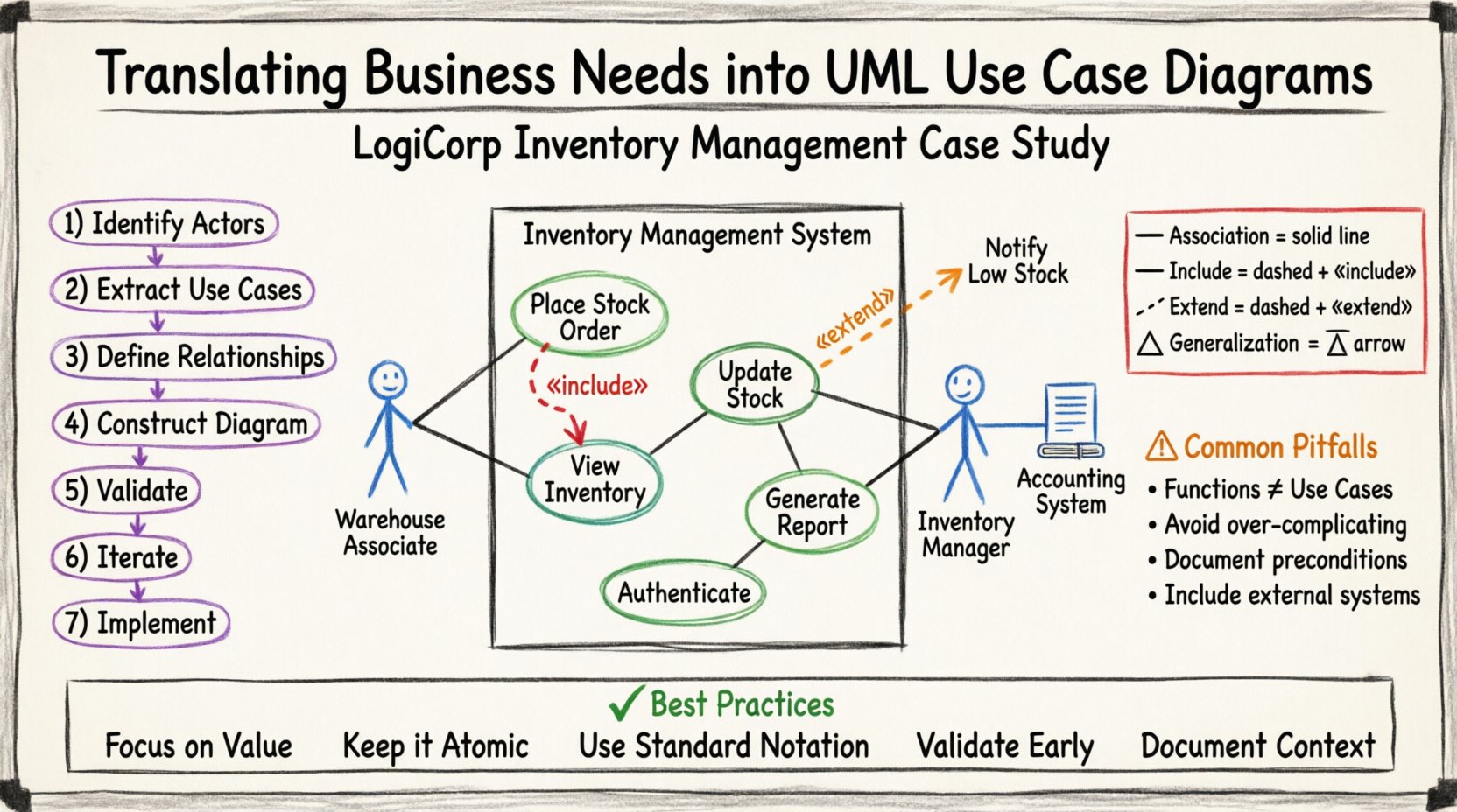
For the LogiCorp system, the diagram structure looks like this:
- System Boundary: Inventory Management System.
- Inside: Update Stock, View Inventory, Generate Report, Authenticate, Place Order.
- Outside: Warehouse Associate, Inventory Manager, Accounting System.
Mapping the Flow
Draw the lines carefully. Ensure no lines cross unnecessarily, as this reduces readability. If lines must cross, use a connector node to show the path clearly.
| Relationship | Symbol | Meaning |
|---|---|---|
| Association | Solid Line | Actor interacts with Use Case |
| Include | Dashed Arrow with «include» | Base Use Case always uses Included Use Case |
| Extend | Dashed Arrow with «extend» | Base Use Case may use Extended Use Case |
| Generalization | Solid Line with Triangle Arrow | Inheritance (Actor or Use Case) |
⚠️ Step 5: Common Pitfalls and Validation
Creating the diagram is only half the work. You must validate it against the real-world constraints. Here are common errors to avoid during this phase.
1. Confusing Functions with Use Cases
A common mistake is listing system buttons as Use Cases. “Click Submit Button” is not a Use Case. “Submit Form” is the action, but the Use Case is the goal behind it, such as “Register User.” Focus on the user’s goal.
2. Over-Complicating Relationships
Do not overuse Include and Extend. If a relationship is optional but frequent, consider making it a separate Use Case instead. Keep the diagram readable for non-technical stakeholders.
3. Ignoring Preconditions
Every Use Case has preconditions. For “Place Order,” the precondition is “User must be logged in.” If this is not met, the Use Case cannot start. Document these in the Use Case specifications, not necessarily on the diagram itself, but keep them in mind.
4. Missing External Systems
In the LogiCorp case, the Accounting System was initially missed. This is a critical error. External systems must be represented as Actors to ensure the integration points are clear.
🔄 Step 6: Iteration and Refinement
The first draft is rarely perfect. You will likely find gaps when stakeholders review the model. This is normal. The diagram is a communication tool, not a final design document.
Review Process
- Walkthrough: Sit with the Warehouse Manager and walk through each Use Case.
- Questioning: Ask “What happens if the internet goes down?” to identify exception flows.
- Adjustment: Add new Actors or Use Cases as discovered.
For example, during the review, the Manager noted that “Stock Adjustment” required a specific approval code. This led to splitting the “Update Stock” Use Case or adding an extension point for “Require Approval.” This level of detail ensures the system handles business rules correctly.
📈 Step 7: Moving to Implementation
Once the diagram is validated, it becomes the input for the development team. The Use Cases guide the creation of user stories and test cases.
- Test Cases: Each Use Case path becomes a test scenario.
- API Design: Actors and Use Cases define the endpoints and data structures.
- Documentation: The diagram serves as the high-level documentation for the system.
By translating business needs into this model early, you reduce the risk of building the wrong features. You ensure that the development effort is directed toward the actual business value.
🎓 Summary of Best Practices
To maintain quality throughout the modeling process, adhere to these core principles:
- Focus on Value: Every Use Case must deliver value to an Actor.
- Keep it Atomic: One Use Case, one goal.
- Use Standard Notation: Stick to standard UML symbols for clarity.
- Validate Early: Show the draft to stakeholders immediately.
- Document Context: Use the diagram as a starting point for detailed specifications.
Translating business needs into a valid UML Use Case Diagram is not just about drawing lines. It is about understanding the business logic and translating it into a technical language that everyone can agree on. This process ensures that the final system meets the actual needs of the organization, reducing waste and increasing efficiency.
When you approach modeling with this level of rigor, you move from guessing requirements to defining them. The diagram becomes a living document that guides the project from concept to deployment.