
Software architecture relies heavily on visual representation to convey complex interactions between system components. Among these, the communication diagram serves as a critical tool for mapping how objects interact to fulfill specific behaviors. However, when these diagrams become cluttered, ambiguous, or logically inconsistent, they stop being a source of clarity and start becoming a source of confusion. This guide addresses the common pitfalls that degrade the utility of communication diagrams and provides a structured approach to troubleshooting and restoring their effectiveness.
Clarity in system design is not just about aesthetics; it is about ensuring that every developer, architect, and stakeholder interprets the flow of data and control in the exact same way. When a diagram fails to communicate its intent, the risk of implementation errors increases significantly. By focusing on structure, logic, and consistency, teams can transform their diagrams from confusing sketches into reliable documentation assets.
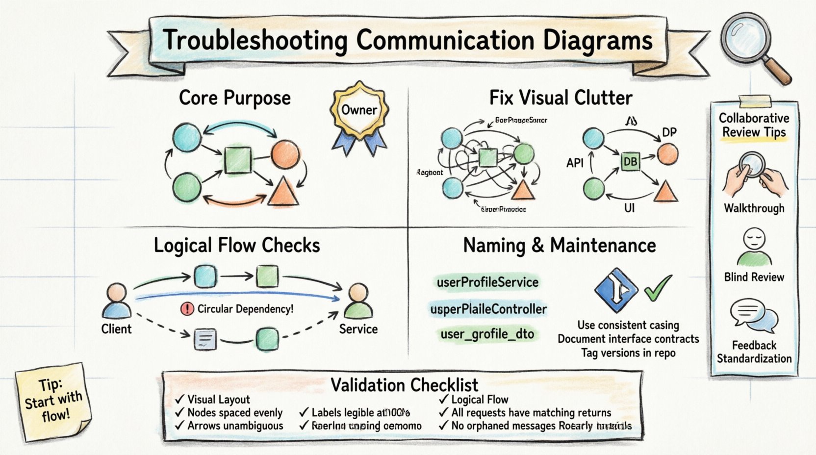
Understanding the Core Purpose 🎯
A communication diagram visualizes the interactions between objects or components in a system. Unlike sequence diagrams, which emphasize the timing of messages, communication diagrams focus on the structural relationships and the flow of information. They are particularly useful for understanding the overall connectivity of a system without getting bogged down in temporal details.
When troubleshooting a diagram that does not make sense, the first step is to return to this fundamental purpose. Ask yourself: Does this diagram clearly show which objects are talking to which other objects, and what is being exchanged? If the answer is no, the foundation is flawed.
- Focus on Connectivity: Are the links between objects clearly defined?
- Focus on Message Flow: Is the direction of information clear?
- Focus on Responsibility: Can you identify which object handles which task?
Confusion often arises when the diagram attempts to do too much. It is better to have a set of focused diagrams than one massive diagram trying to cover every interaction. If a diagram feels crowded, consider splitting it by functional area or use case.
Visual Clutter and Layout Issues 📐
One of the most common reasons a communication diagram fails to communicate is visual clutter. When lines cross over each other, labels overlap, or objects are placed haphazardly, the cognitive load required to read the diagram increases. This leads to misinterpretation and errors.
1. Crossing Lines and Ambiguous Paths
In diagramming tools, lines representing links or messages can easily cross. When this happens, it becomes difficult to determine which message belongs to which link. To troubleshoot this:
- Reposition Objects: Move the nodes (objects) so that connecting lines do not intersect unnecessarily. Use a grid or alignment guides to help organize the layout.
- Route Curved Lines: If straight lines must cross, consider using curved paths to distinguish between different connections.
- Label Placement: Ensure message labels are placed near the middle of the arrow, not on top of another line or object.
2. Missing Arrowheads or Direction Indicators
Directionality is crucial. An arrow pointing from Object A to Object B implies a message flow in that direction. If the arrowhead is missing or faint, the receiver and sender roles become ambiguous.
- Check Arrowheads: Verify that every interaction has a clear start and end point marked by an arrowhead.
- Consistent Styling: Ensure all arrows use the same style. Mixing solid lines with dashed lines without a legend can confuse the reader about the type of message (e.g., synchronous vs. asynchronous).
3. Overcrowded Labels
Too much text on a single diagram makes it unreadable. Long method names or detailed descriptions should be minimized on the diagram itself.
- Use Abbreviations: Use standard abbreviations for common terms (e.g., “Get” instead of “Retrieve Data”), provided the team agrees on the meaning.
- External Documentation: If a message requires complex logic, reference a separate specification document rather than writing the logic on the diagram.
Logical Flow and Sequence Errors 🔄
Even if a diagram looks clean, it may still be logically broken. A diagram that depicts interactions that cannot happen in the real system is worse than no diagram at all. Troubleshooting logical errors requires analyzing the flow of control and data.
1. Missing Return Messages
Communication diagrams often focus on the outgoing messages but forget the return values. If Object A calls a method on Object B, Object B must return a result or status. Without this, the interaction is incomplete.
- Verify Responses: For every request message, check if a corresponding return message exists.
- Distinguish Types: Use different line styles for requests and returns (e.g., solid for request, dashed for return) to make the cycle visible.
2. Circular Dependencies
While some loops are necessary, circular dependencies where Object A calls Object B, and Object B immediately calls Object A without an exit condition, can indicate a design flaw.
- Trace the Path: Follow the lines from one object to another. If you return to the start without reaching a terminal state, the flow is problematic.
- Identify the Loop: If a loop is intentional (e.g., a retry mechanism), ensure it is clearly marked with a loop label or a guard condition.
3. Incorrect Object Roles
Confusion often stems from an object playing two conflicting roles. For example, if the “User Interface” object is also responsible for “Data Validation” and “Database Connection,” the diagram may show it interacting with itself in ways that blur responsibility boundaries.
- Check Responsibilities: Ensure each object has a distinct purpose. If an object interacts with itself excessively, consider splitting it into two separate components.
- Review Interfaces: Verify that the object is requesting methods that actually exist on the target object.
Object Identification and Naming 🏷️
Consistency in naming is the glue that holds a communication diagram together. If object names change between diagrams, or if the same object is referred to by different names in different parts of the same diagram, the reader loses the thread.
1. Inconsistent Naming Conventions
One section of the diagram might refer to a component as “AuthService,” while another calls it “AuthenticationManager.” This inconsistency suggests that the diagram was created by multiple people without a unified standard.
- Establish a Glossary: Create a shared vocabulary for component names. Use domain-driven design terms where possible.
- Global Search: Use your diagramming tool’s search function to find all instances of a name. Ensure they match exactly.
2. Vague or Generic Names
Labels like “System,” “Manager,” or “Handler” are often too generic to be useful. They do not tell the reader what the object actually does.
- Be Specific: Use names that describe the function, such as “OrderProcessor” instead of “OrderManager.”
- Contextual Names: If an object is used in a specific context (e.g., “PaymentGateway”), ensure the name reflects that context.
3. Missing Object Instances
Communication diagrams often show classes (e.g., “Customer”) rather than instances (e.g., “Customer #12345”). While showing instances is more precise, it can make diagrams messy. The key is to maintain clarity regarding whether you are showing a general interaction pattern or a specific scenario.
- Define the Scope: State clearly at the top of the diagram whether it depicts a class-level interaction or a specific instance scenario.
- Standardize Notation: If using instance notation (underlined names), ensure it is consistent across all diagrams in the project.
The Validation Checklist ✅
Before finalizing a communication diagram, run it through a structured validation process. This table outlines the critical checks to ensure the diagram is accurate and understandable.
| Category | Check Question | Pass/Fail |
|---|---|---|
| Visual Layout | Do lines cross without clear distinction? | |
| Visual Layout | Are all arrowheads visible and consistent? | |
| Logical Flow | Do all request messages have return messages? | |
| Logical Flow | Is there an unexplained circular dependency? | |
| Naming | Are object names consistent across the diagram? | |
| Naming | Do names accurately reflect responsibilities? | |
| Completeness | Is the diagram focused on a single use case? | |
| Completeness | Are all relevant external systems included? |
Using this checklist during peer reviews can significantly reduce the number of errors that make it into the final documentation.
Maintenance and Lifecycle Management 🛠️
Diagrams are not static artifacts. As the system evolves, the diagrams must evolve with them. A diagram that is accurate today may be obsolete tomorrow if the code changes without the documentation being updated. This “diagram rot” is a major source of confusion for new team members.
1. Version Control Integration
Just as source code is versioned, diagrams should be treated as versioned assets. Store diagram files in the same repository as the codebase.
- Link to Code: Reference specific commit hashes or feature branches when updating a diagram.
- Change Logs: Maintain a log of when and why a diagram was updated. This helps trace the history of architectural decisions.
2. Automated Generation Considerations
One effective way to prevent diagram rot is to generate diagrams from the code itself, where possible. While manual diagrams offer more abstraction, automated diagrams ensure that the structure matches the implementation.
- Hybrid Approach: Use automated tools for structural accuracy and manual tools for high-level conceptual flows.
- Sync Checks: Implement a CI/CD check that warns if the diagram file has not been updated recently relative to code changes.
3. Regular Review Cycles
Schedule regular reviews of the documentation alongside code reviews. This ensures that if a developer changes a critical interaction, the diagram is updated at the same time.
- Design Meetings: Dedicate time in sprint planning to review architectural diagrams.
- Onboarding: Use the diagrams as a primary resource for new hires. If they find them confusing, it is a signal to update the documentation.
Collaborative Review Strategies 🤝
Even with a perfect checklist, human error is inevitable. Collaborative review is the final line of defense against confusing diagrams. The goal is to create an environment where questioning a diagram is encouraged.
1. The Walkthrough Method
Conduct a walkthrough where a presenter traces the flow of a message from start to finish, and the reviewers follow along on their own copies.
- Role Play: Assign roles to objects (e.g., “I am the User,” “I am the Database”) and act out the interaction.
- Challenge Assumptions: Ask questions like, “What happens if this message fails?” or “Does this object really need to know about that other object?”
2. Independent Verification
Have a team member review the diagram without the presenter present. This removes the bias of the creator explaining away ambiguities.
- Blind Review: Ask the reviewer to annotate what they find unclear without asking the author for help.
- Feedback Loop: Use the annotations to refine the diagram before the next development cycle.
3. Standardizing Feedback
To avoid subjective criticism, establish standard feedback categories. This helps focus the discussion on technical accuracy rather than personal preference.
- Accuracy: Does it match the code or requirements?
- Clarity: Is it easy to read and understand?
- Completeness: Are all necessary interactions shown?
- Consistency: Does it match the style of other diagrams?
Conclusion: Building Trust Through Clarity 🏗️
The value of a communication diagram lies in its ability to build shared understanding. When a diagram is confusing, it erodes trust in the documentation and the team’s design process. By systematically addressing visual clutter, logical gaps, naming inconsistencies, and maintenance issues, teams can ensure their diagrams remain accurate and useful.
Investing time in troubleshooting these diagrams pays dividends in reduced debugging time, smoother onboarding, and fewer implementation errors. Treat your diagrams as living documents that require the same care and attention as the code they describe. With a disciplined approach to validation and review, your communication diagrams will become a reliable source of truth for your entire project.