
Creating a Use Case Diagram is often viewed as a technical checkpoint in the systems engineering lifecycle. However, when a diagram lands on a stakeholder’s desk and is met with silence or confusion, the issue is rarely about the syntax. It is about communication. A model that fails to resonate with the business side of the organization is not just an aesthetic failure; it is a strategic risk. Weak diagrams create ambiguity in requirements, leading to scope creep, development errors, and ultimately, product failure. This guide addresses the root causes of stakeholder rejection and provides actionable strategies to fortify your modeling efforts.
🧐 The Core Disconnect: Technical Precision vs. Business Value
Many analysts fall into the trap of prioritizing UML compliance over stakeholder comprehension. A diagram can be perfectly valid according to the standard yet fail to convey the intended business logic. Stakeholders do not typically care about the specific cardinality of an association unless it directly impacts their operational understanding. They care about the flow of value, the identity of the participants, and the clarity of the interactions. When a model focuses too heavily on technical implementation details, it obscures the business intent.
The Business View: Stakeholders want to see how their roles interact with the system to achieve goals.
The Technical View: Developers need to see the boundaries and the specific triggers for execution.
The Analyst View: You must bridge these two perspectives without diluting the rigor of the model.
When these perspectives clash, the diagram becomes a source of friction. To troubleshoot this, we must first identify the specific structural weaknesses that lead to rejection.
📐 Troubleshooting Scope and Granularity
The most common reason for diagram rejection is an inappropriate level of detail. This manifests in two opposing ways: the diagram is too abstract, or it is too granular.
1. The “Black Box” Problem
When a diagram is too high-level, stakeholders see a single use case labeled “Process Order” connected to an actor “Customer.” This lacks the necessary context to validate requirements. Stakeholders cannot verify if the system handles refunds, cancellations, or partial shipments. They see a box, not a process.
Symptom: Stakeholders ask, “What about edge cases?” or “How do we handle exceptions?”
Fix: Decompose the use case. Break “Process Order” into “Select Items,” “Apply Payment,” and “Confirm Delivery.” This allows stakeholders to validate specific business rules within each step.
2. The “Implementation Detail” Trap
Conversely, some models dive too deep too quickly. Including steps like “Click Button X” or “Database Query ID 500” violates the abstraction level expected in a Use Case Diagram. These are interaction details, not functional requirements. If a stakeholder sees technical implementation steps, they may feel the model is too prescriptive, limiting future flexibility.
Symptom: Stakeholders argue about UI layout or specific database schemas during a requirements review.
Fix: Strip the diagram down to the goal-oriented actions. Keep the “what,” not the “how.” Focus on the outcome of the interaction rather than the mechanism.
👥 Clarifying Actor Definitions
Actors represent the roles that interact with the system. Ambiguity here is a primary driver of confusion. If the definition of an actor is vague, the use cases associated with them become unstable.
1. Human vs. System Actors
It is common to mix external human roles with internal system components. For example, having a “Payment Gateway” as an actor is technically correct but often confusing if not distinguished from a “Payment Processor” role. Stakeholders need to know who is responsible for what action. Is the system initiating the action, or is the external entity?
Rule: Clearly label actors as either Human (e.g., “Customer,” “Admin”) or System (e.g., “Email Server,” “Legacy Database”).
Benefit: This clarifies responsibility boundaries. If a stakeholder sees “Email Server,” they understand it is an automated trigger, not a human task.
2. Role Generalization
Using generalization relationships to group actors can save space, but it often introduces ambiguity. If you generalize “Manager” and “Staff” into “Employee,” you lose the distinction in permissions. A “Manager” might approve a request, while a “Staff” member only submits it. Collapsing these into a generic “Employee” actor hides critical business rules.
Recommendation: Only generalize actors if they share the exact same set of use cases. If one actor can do something another cannot, keep them separate.
🔗 Relationships and Interactions
The connections between actors and use cases tell the story of the system. Misusing relationships like Include, Extend, and Generalization leads to logical gaps that stakeholders will inevitably spot.
1. The Abuse of “Include”
An Include relationship implies that the included use case is a mandatory part of the base use case. A common error is using Include for optional steps or alternatives. If you include “Validate Login” into “Access Account,” it implies you cannot access the account without validation. However, if you use Include for “Show Help,” you imply the help screen is mandatory every time, which is incorrect.
Check: Ask, “Can the base use case complete without this step?” If yes, do not use Include.
2. The “Extend” Confusion
Extend relationships are for optional behavior or error handling. They should be used sparingly. Overusing Extend makes the diagram look cluttered and hard to read. Stakeholders often struggle to understand the extension point unless it is clearly marked. Furthermore, too many extensions suggest the system is fragile or exception-heavy.
Strategy: Use Extend only for distinct alternative flows that deviate significantly from the main path. For minor variations, describe them in the text, not the diagram.
3. Association Cardinality
While UML supports cardinality (e.g., 1..* or 0..1), using these in Use Case Diagrams can be misleading. Stakeholders often interpret cardinality as data volume rather than participation frequency. It is better to rely on clear labeling or accompanying text to explain frequency. For example, “One-time setup” is better described in text than as a cardinality constraint on the line.
📊 Common Pitfalls vs. Solutions
The following table summarizes frequent errors found in stakeholder-rejected models and the corresponding remediation strategies.
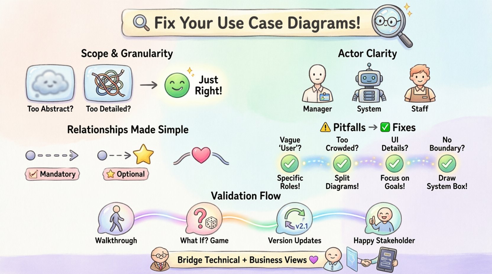
⚠️ Common Pitfall | 🔍 Stakeholder Reaction | 🛠 Corrective Action |
|---|---|---|
Using vague actor names like “User” | “Who exactly is this? Is it an admin or a guest?” | Define specific roles (e.g., “Registered User,” “Guest,” “Administrator”). |
Too many use cases on one diagram | “This is overwhelming. I can’t see the main flow.” | Split into sub-system diagrams. Focus on one domain per view. |
Confusing “Extend” with “Include” | “Is this step required or optional?” | Review logic: Mandatory = Include, Optional = Extend. |
Including UI elements (buttons, screens) | “This is a UI wireframe, not a process model.” | Remove UI details. Focus on functional goals and actions. |
No system boundary defined | “What is inside the system and what is outside?” | Draw a clear rectangle boundary. Label external entities outside, internal processes inside. |
Ignoring non-functional requirements | “How does the system handle security or speed?” | Note constraints in the text appendix. Do not clutter the diagram with security actors unless critical. |
🗣 The Validation Process: Getting Buy-In Early
Waiting until the final review to present a Use Case Diagram is a recipe for rejection. By then, too much time has been invested, and stakeholders feel the model represents a finished decision rather than a discussion tool. The goal is to use the diagram as a conversation starter.
1. The Walkthrough Approach
Instead of emailing the diagram and waiting for feedback, schedule a walkthrough session. Walk through the diagram chronologically. Start with the primary actor and the main success scenario. Ask the stakeholder to confirm the steps as you trace them.
Technique: Use a pointer or digital highlight. “When the customer clicks submit, the system validates the payment. Does this match your expectation?”
Benefit: This forces immediate engagement. Ambiguities are caught in real-time.
2. The “What If” Game
Stakeholders often think in terms of exceptions. Use the diagram to probe these thoughts. “What happens if the payment fails?” Trace that path. If you haven’t modeled it, acknowledge it. “We don’t see that here yet. Should we add an exception flow?” This demonstrates that you are listening and adapting, rather than enforcing a static model.
3. Versioning and Change Control
Models evolve. Stakeholders might request a change three weeks after the initial review. Treat the diagram as a living document. Maintain version history. When a change is made, explicitly highlight what changed. This builds trust. Stakeholders appreciate knowing that their feedback was incorporated and not lost in a revision.
🧩 Contextualizing the Diagram
A Use Case Diagram rarely stands alone. It is part of a larger requirements package. Without context, the diagram can be misinterpreted. Ensure the diagram is accompanied by supporting documentation.
1. Use Case Descriptions
Every use case should have a corresponding text description. This text should include preconditions, postconditions, and the main success scenario. The diagram provides the map; the text provides the terrain. Without the text, the diagram is a skeleton without flesh.
Content: Include specific business rules, validation logic, and data requirements.
Format: Keep it consistent. Use a standard template for every use case description.
2. Cross-References
Link the diagram to other artifacts. If a use case relies on a specific data entity, link to the data model. If it triggers a specific security protocol, link to the security requirements. This creates a network of truth. Stakeholders can trace the lineage of a requirement from the high-level diagram down to the technical specification.
🔄 Iterative Refinement
Perfection is not the enemy of good; it is the enemy of done. Do not aim for a perfect diagram on the first draft. Aim for a clear draft that facilitates discussion. Use the feedback loop to refine the model.
Iterate: Expect to revise the diagram multiple times. Early versions are for discovery. Late versions are for verification.
Focus: Prioritize the high-value use cases. If you have 50 use cases, focus the stakeholder’s attention on the 10 that drive the most business value.
Clarity: If a line looks tangled, redraw it. Visual clutter is a silent killer of comprehension. White space is a tool, not a waste of space.
🎯 Final Thoughts on Model Integrity
The rejection of a Use Case Diagram is rarely an attack on the analyst. It is a signal that the communication channel is broken. By addressing scope, clarifying actors, and refining relationships, you transform the diagram from a technical artifact into a business tool. The goal is not to create a diagram that looks pretty on paper, but one that aligns the expectations of the business and the engineering teams.
When stakeholders engage with the model confidently, asking questions about edge cases rather than definitions, you know the troubleshooting is complete. The model has done its job. It has facilitated understanding. It has aligned the vision. This is the true measure of a successful Use Case Diagram.
Keep the focus on value. Keep the model clean. Keep the conversation open. In doing so, you ensure that the system you build is the system the business actually needs.