
Designing a secure and reliable authentication system requires more than just checking a username and password against a database. It demands a structured understanding of how a system behaves over time. This is where the UML State Diagram, also known as a State Machine Diagram, becomes indispensable. By visualizing the lifecycle of a user session, developers can anticipate edge cases, prevent security vulnerabilities, and ensure consistent behavior across different platforms.
In this comprehensive guide, we will explore how to model a login system using state machine logic. We will move beyond simple flowcharts to define states, transitions, events, and guard conditions. The goal is to create a robust model that handles success, failure, timeouts, and lockouts without ambiguity.
🧠 Understanding State Machine Diagrams
A State Machine Diagram is a behavioral model that describes the distinct conditions under which a system or object exists at any given time. Unlike an activity diagram, which focuses on the flow of actions, a state diagram focuses on the status of the system and how it changes.
Core Components
- State: A condition during which the object meets requirements to perform some activity or wait for events. Examples include Logged Out, Authenticating, or Account Locked.
- Transition: The movement from one state to another. This is triggered by an event.
- Event: Something that happens at a specific time that triggers a transition. Examples include Submit Credentials or Session Timeout.
- Guard Condition: A Boolean expression that must evaluate to true for the transition to occur. For example,
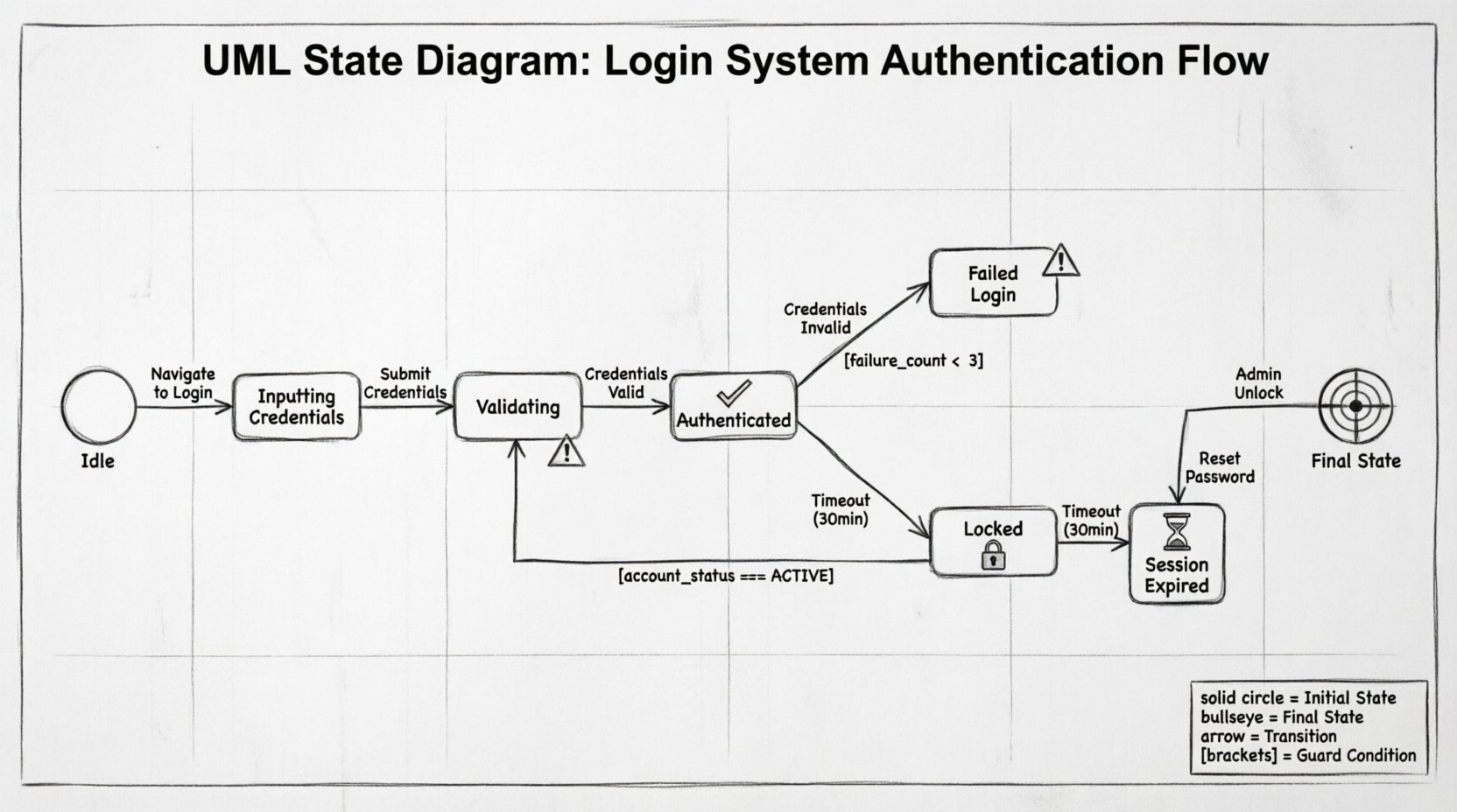
max_attempts < 3. - Initial State: The starting point of the system, usually represented by a solid circle.
- Final State: The termination point, represented by a solid circle inside a larger circle.
When applied to authentication, these components define the exact rules for how a user interacts with the system. This clarity is vital for developers, testers, and stakeholders to agree on the system behavior before a single line of code is written.
📋 The Login System Scenario
Consider a web-based application requiring secure access. The system must manage the following requirements:
- Users must authenticate before accessing protected resources.
- Invalid credentials should trigger a retry mechanism.
- Repeated failures must result in a temporary lockout.
- Active sessions must expire after a period of inactivity.
- Users must be able to reset their password if forgotten.
A linear flowchart would struggle to represent the concurrency of a session timeout while a user is actively typing. A state diagram excels here because it explicitly defines the state of the session at any moment.
🏗️ Modeling the States
To build the diagram, we first identify the discrete states the system can occupy. The following table outlines the primary states for our authentication model.
| State Name | Description | Entry Action |
|---|---|---|
| Idle | The system is waiting for user interaction. No active session exists. | Clear previous session data |
| Inputting Credentials | User has provided a username and is entering a password. | Enable input fields |
| Validating | System is processing the credentials against the security store. | Disable UI to prevent double submission |
| Authenticated | User has successfully logged in and has access to resources. | Create session token |
| Failed Login | Authentication attempt was rejected due to invalid data. | Increment failure counter |
| Locked | Account is temporarily disabled due to excessive failures. | Log security event |
| Session Expired | Valid session ended due to timeout or manual logout. | Destroy session token |
🔄 Defining Transitions and Events
Once states are defined, we map the transitions between them. These transitions are driven by specific events. The logic governing these moves ensures the system behaves predictably.
1. The Login Flow
- From Idle to Inputting Credentials: Triggered when the user navigates to the login page.
- From Inputting Credentials to Validating: Triggered when the user clicks the Sign In button.
- From Validating to Authenticated: Triggered if credentials match and the account is not locked.
- From Validating to Failed Login: Triggered if credentials do not match.
2. The Failure and Lockout Logic
This is where state diagrams provide significant value over simple if-else logic. We need to track the number of failures within a specific window.
- From Failed Login to Validating: Triggered when the user attempts to log in again immediately.
- From Failed Login to Locked: Triggered if the failure count exceeds the threshold (e.g., 3 attempts) within 15 minutes.
- From Locked to Idle: Triggered after the lockout duration expires, or when an administrator manually resets the account.
🛡️ Guard Conditions and Security
Guard conditions are critical for security. They act as filters on transitions. A transition cannot occur unless the guard condition evaluates to true.
Example: Lockout Prevention
Consider the transition from Failed Login to Validating. We do not want this to happen if the user is already locked. The guard condition would look like:
account_status == ACTIVE AND failure_count < 3
If the account is in the Locked state, this transition is blocked. The system must instead direct the user to a Locked state or a recovery flow.
Session Timeout Logic
Security best practices dictate that sessions should not last indefinitely. We introduce a time-based event. Even if the user is in the Authenticated state, a Timeout event can occur.
- Transition: Authenticated ➝ Session Expired.
- Event: Timer expires (e.g., 30 minutes of inactivity).
- Guard: None (time is absolute).
This ensures that even if a user leaves their device unattended, the system automatically reverts to a secure state.
🧩 Handling Edge Cases
A robust model accounts for scenarios that deviate from the standard path. These edge cases often hide the most critical bugs.
1. The Password Reset Flow
If a user forgets their password, they should not be stuck in the Failed Login loop. The state diagram must allow a transition from Idle or Failed Login to a Password Reset Request state.
- Transition: Idle ➝ Reset Request.
- Event: User clicks Forgot Password.
- Outcome: A token is generated, and the user is moved to a Reset Pending state.
2. Concurrent Requests
What happens if a user clicks the Sign In button twice rapidly? Without state management, the system might process two authentication requests simultaneously. The Validating state should have a guard condition preventing re-entry while already in that state.
- Rule: If state is Validating, ignore subsequent Submit Credentials events.
3. Network Interruptions
If the network drops during the Validating phase, the user might not receive a response. The state machine should have a timeout event for the Validating state.
- Transition: Validating ➝ Failed Login.
- Reason: Connection timeout.
💻 Mapping to Code Logic
Translating a UML State Diagram into application logic requires careful architectural planning. There are generally two approaches: implementing a state machine library or writing explicit state management code.
Approach A: Explicit State Management
In this approach, the current state is stored in the session or database. Every request checks the current state before processing.
- Database: A field
current_statetracks the status. - Logic: A switch statement or series of if-else blocks handles the transition logic based on the event.
- Benefit: High visibility; easy to debug by checking the database field.
- Drawback: Can become complex if many states exist.
Approach B: Event-Driven State Machine
Here, the application uses a pattern where events are dispatched, and listeners handle transitions.
- Library: A framework handles the state definition and transitions.
- Configuration: The UML diagram is often converted into a configuration file.
- Benefit: Decouples logic from control flow; easier to scale.
- Drawback: Requires learning specific patterns or libraries.
⚠️ Common Pitfalls in State Modeling
Even experienced architects make mistakes when modeling authentication flows. Being aware of these common errors helps ensure the integrity of the system.
1. Deadlocks
A deadlock occurs if the system reaches a state with no valid transitions. For example, if a user is locked, but no transition exists to unlock them automatically, the account is permanently inaccessible until manual intervention. Always ensure every state has an exit path.
2. Ambiguous Transitions
Ensure there is only one valid transition for a specific event in a specific state. If both Validating and Inputting respond to Submit Credentials, the system behavior becomes unpredictable.
3. Ignoring the Idle State
Many models skip the Idle state and start directly at login. However, the Idle state is crucial for defining the initial conditions and cleaning up resources. It represents the system in a neutral, ready-to-accept-input posture.
4. Overlooking Security Events
Security events like Brute Force Detected should be modeled as transitions that override normal flow. If the system detects suspicious activity, it should force a transition to a Locked or Verification Required state immediately, regardless of the current user action.
🔍 Debugging and Validation
Once the state diagram is designed, it serves as a blueprint for testing. Testers can use the diagram to create a checklist of scenarios.
- Scenario 1: Start at Idle. Submit wrong password. Verify transition to Failed Login.
- Scenario 2: Start at Failed Login. Submit wrong password again. Verify failure count increments.
- Scenario 3: Start at Authenticated. Wait 30 minutes. Verify transition to Session Expired.
- Scenario 4: Start at Locked. Try to log in. Verify transition is blocked or redirects to recovery.
By validating the code against these states, teams can ensure that the implementation matches the design. This reduces the likelihood of logic errors making it into production.
📈 Benefits of State Machine Modeling
Why invest time in creating a UML State Diagram? The advantages extend beyond documentation.
1. Clear Communication
Visual models bridge the gap between developers, product managers, and security auditors. Everyone can see the exact behavior expected without reading complex requirements documents.
2. Improved Security Posture
By explicitly modeling lockouts and timeouts, security vulnerabilities like session hijacking or brute force attacks are mitigated by design rather than as an afterthought.
3. Easier Maintenance
If business rules change (e.g., lockout time increases from 15 to 30 minutes), the change is reflected in the guard conditions of the diagram. Developers can update the code with a clear understanding of what needs to change.
4. Comprehensive Testing
Test coverage becomes more systematic. Instead of guessing which paths to test, testers follow the transitions defined in the diagram to ensure every state is reachable and every transition works correctly.
🛠️ Final Considerations for Implementation
When moving from design to implementation, keep the following points in mind to maintain the integrity of the state model.
- Persist State: Ensure the state is saved to the database or session store. If the server restarts, the user should not lose their place in the authentication flow.
- Log Transitions: Every time a transition occurs, especially security-related ones like Failed Login or Locked, log the event with a timestamp and user ID. This is vital for auditing.
- Handle Concurrency: If a user logs in from two different devices, the state machine must handle the conflict. Typically, the latest session invalidates the previous one.
- Graceful Degradation: If the state machine logic fails, the system should default to a secure state (e.g., deny access) rather than granting access by mistake.
Designing a login system is not just about verifying a password; it is about managing the lifecycle of trust between the user and the application. A UML State Diagram provides the structure needed to manage this lifecycle with precision. By defining states, events, and transitions clearly, you create a system that is secure, maintainable, and predictable.
As you apply these concepts to your own projects, remember that the diagram is a living document. It should evolve as requirements change and as new edge cases are discovered during testing. This iterative approach ensures that the authentication logic remains robust over time.