
Designing a robust banking application requires more than just writing code. It demands a clear understanding of how users interact with the system. Visualizing these interactions is crucial for system analysts and developers alike. A UML Use Case Diagram serves as a blueprint for these interactions, mapping out the functional requirements without getting bogged down in implementation details. This guide provides a detailed walkthrough on constructing a complete UML Use Case Diagram tailored for a banking system context.
Whether you are a student learning software modeling or a professional refining system architecture, understanding the relationship between actors and system functions is foundational. We will explore the core components, the step-by-step construction process, and the specific nuances of banking logic. By the end of this article, you will have a solid framework for modeling complex financial interactions.
🔍 Understanding the Core Components
Before drawing lines and circles, it is essential to define the vocabulary of Use Case Diagrams. These diagrams rely on three primary elements: Actors, Use Cases, and the System Boundary.
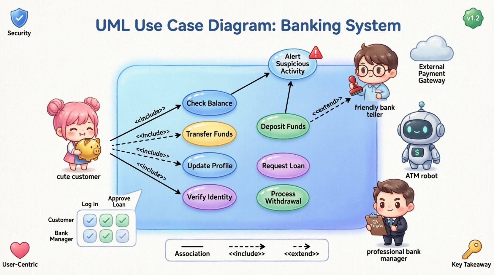
- Actors: These represent the roles that interact with the system. They can be human users, external hardware, or other software systems. In a banking context, examples include Customers, Bank Tellers, and Automated Teller Machines.
- Use Cases: These represent specific goals or actions a user can perform. They are the functional units of the system. Examples include “Transfer Funds,” “Check Balance,” or “Generate Monthly Statement.”
- System Boundary: This is the box that encloses the use cases. It defines what is inside the system and what is outside. Everything within the boundary is a function the system provides; everything outside is an actor or external dependency.
Clarity in these definitions prevents ambiguity during the development phase. A well-defined boundary ensures that the team agrees on what features are being built versus what is managed by external parties.
🚀 Step 1: Define the Scope and Boundary
The first step in modeling a banking system is establishing the scope. What is this specific banking system responsible for? Is it the core ledger? The mobile application? The branch management interface? For this guide, we assume a comprehensive system covering both digital and physical interactions.
Draw a rectangle on your modeling canvas. This rectangle represents the System Boundary. Label it clearly, such as “Core Banking System.” All subsequent use cases must exist inside this box. If a function, like “SMS Notification,” is triggered by the system but performed by an external carrier, it remains outside the boundary, connected by a line.
👥 Step 2: Identify the Actors
Identifying actors is often the most critical part of the design process. You must ask: “Who or what interacts with this system to achieve a goal?” In a banking environment, actors are diverse.
Primary vs. Secondary Actors
- Primary Actors: These are the users who initiate the transactions to get value from the system. For a bank, the primary actor is usually the Customer.
- Secondary Actors: These are systems or users that support the primary actor or are supported by the system. Examples include the Payment Gateway or the Internal Audit System.
Specific Banking Actors
Here is a breakdown of potential actors for a complete banking model:
- Customer: The individual managing their personal finances.
- Teller: A bank employee assisting customers in a physical branch.
- ATM Machine: A hardware device providing self-service options.
- Bank Manager: An administrative role with oversight capabilities.
- External Payment Gateway: A third-party service for processing transfers.
Ensure you do not model specific individuals (e.g., “John Doe”). Model roles instead. Roles remain consistent even if the personnel changes.
🎯 Step 3: Identify the Use Cases
Once actors are placed outside the system boundary, you must define what they do. Use cases should be named using a verb-noun structure, such as “Withdraw Cash” rather than just “Withdrawal.”
Customer Use Cases
These are the most common interactions in a banking system:
- Log In: Authentication to access the account.
- Check Balance: Viewing current available funds.
- Transfer Funds: Moving money between accounts or to external parties.
- Deposit Funds: Adding money via check or cash deposit.
- Request Loan: Initiating a credit application.
- Update Profile: Changing contact information or passwords.
Teller and Manager Use Cases
Internal roles have different access levels and functions:
- Process Withdrawal: Handling cash requests at a counter.
- Verify Identity: Validating customer credentials physically.
- Approve Loan Application: A specific workflow for credit management.
- Generate Reports: Creating compliance or transaction logs.
It is vital to avoid creating use cases that are too granular (like “Click Button A”) or too broad (like “Manage Bank”). Keep the focus on user goals.
🔗 Step 4: Establish Relationships
Connecting actors to use cases creates the logic of the system. There are three main types of relationships in UML Use Case Diagrams: Association, Include, Extend, and Generalization.
1. Association
This is a direct line connecting an actor to a use case. It indicates that the actor participates in that use case. For example, a Customer is associated with “Log In” and “Transfer Funds.”
2. Include Relationship
An include relationship indicates that one use case incorporates the behavior of another. This is typically used for mandatory steps. A common example in banking is authentication.
- Scenario: Most use cases require the user to be logged in.
- Implementation: You can create a “Log In” use case and have other use cases (like “Transfer Funds”) include it.
- Benefit: This reduces redundancy. If the login logic changes, you update it in one place.
3. Extend Relationship
An extend relationship indicates an optional behavior that happens under specific conditions. It adds functionality to a base use case.
- Scenario: A “Transfer Funds” use case might trigger an “Alert Suspicious Activity” use case if the amount exceeds a limit.
- Condition: The extension only occurs if the specific condition (amount > $10,000) is met.
- Benefit: It keeps the main flow clean while acknowledging exceptions.
4. Generalization
This represents inheritance. One actor or use case is a specialized version of another.
- Actor Example: “Premium Customer” is a specialization of “Customer.” Premium customers might have access to “Request Wire Transfer,” which regular customers do not.
- Use Case Example: “Internal Transfer” is a specialization of “Transfer Funds.”
📊 Mapping Actors to Functions
To ensure clarity, a matrix table is often helpful during the design phase. This table maps which actors can perform which use cases.
| Actor | Check Balance | Transfer Funds | Generate Report | Approve Loan |
|---|---|---|---|---|
| Customer | Yes | Yes | No | No |
| Teller | Yes | Yes | Yes | No |
| Bank Manager | Yes | No | Yes | Yes |
| ATM Machine | Yes | Yes (Limited) | No | No |
This matrix helps identify gaps. For instance, if a use case has no actors associated with it, it is an orphan function that should be removed. If an actor has no use cases, they might not be necessary for the system scope.
⚠️ Common Pitfalls in Banking Models
Even experienced analysts make mistakes when modeling complex financial systems. Being aware of these common errors helps improve the quality of your diagram.
- Too Much Detail: Do not model every click or screen. A use case represents a complete goal, not a UI interaction. “Log In” is a use case; “Enter Password” is a step within that use case.
- Ignoring External Systems: Banking rarely exists in a vacuum. Remember to include external dependencies like Credit Bureaus or Payment Processors as actors or systems.
- Confusing Include and Extend: Remember that Include is mandatory, and Extend is optional. A common error is making a security check optional via Extend when it should be mandatory via Include.
- Missing Security Roles: Banking requires strict access control. Ensure that roles like “Auditor” or “Compliance Officer” are represented if they interact with the system.
- Overlapping Boundaries: Be careful not to include business logic that belongs to a different subsystem. Keep the boundary consistent with the project scope.
🛠️ Step 5: Refinement and Validation
Once the initial diagram is drafted, the refinement phase begins. This involves reviewing the model with stakeholders to ensure accuracy.
Validation Checklist
- Are all actors clearly labeled?
- Is every use case reachable by at least one actor?
- Are the relationships (Include/Extend) logically sound?
- Does the system boundary accurately reflect the scope?
- Are there any circular dependencies?
Iterative Process
Modeling is rarely linear. As you discover new requirements during development, you may need to add new use cases or adjust relationships. This is normal. The diagram should evolve alongside the system design.
🔐 Security Considerations in Use Cases
Security is paramount in banking software. While Use Case Diagrams do not show detailed security protocols, they must reflect access control requirements.
- Authentication: Ensure that sensitive use cases like “Change Password” or “View Transaction History” are clearly linked to the authenticated actor.
- Authorization: Use Generalization to show that specific roles (e.g., “Manager”) have access to functions that others (e.g., “Customer”) do not.
- Audit Trails: Consider adding use cases for “Generate Audit Log” to ensure compliance with financial regulations.
By explicitly modeling these interactions, the development team understands that security is a functional requirement, not just an infrastructure concern.
📝 Best Practices for Maintenance
A diagram is a living document. It must remain useful throughout the lifecycle of the project.
- Version Control: Save versions of your diagram as requirements change. This allows you to track how the system scope has evolved over time.
- Documentation: Don’t rely on the diagram alone. Usecase descriptions should accompany the visual model. Describe the preconditions, postconditions, and main flow for complex use cases.
- Standardization: Ensure your team uses consistent naming conventions. If one analyst names a use case “Login,” another should not name it “Authentication.”
💡 Advanced Scenarios
Some banking scenarios require more nuanced modeling. Here are a few examples of how to handle complexity.
Multi-Channel Banking
A customer might interact via Mobile App, Web Browser, or ATM. You can model this by having a general “Customer” actor connect to all channels, or create specific actors like “Mobile User” and “Web User” if their capabilities differ significantly.
Third-Party Integration
Many banks offer bill pay services through third-party aggregators. In this case, the “Third-Party Service” becomes an actor. The “Pay Bill” use case includes a dependency on this external actor.
📌 Summary of Key Takeaways
- Focus on Goals: Use cases represent user goals, not system processes.
- Clear Boundaries: Define what is inside and outside the system early.
- Role-Based Actors: Model roles, not specific individuals.
- Relationship Clarity: Distinguish between mandatory (Include) and optional (Extend) behaviors.
- Iterative Design: Expect to refine the diagram as requirements mature.
Building a UML Use Case Diagram for a banking system is a foundational skill in software engineering. It bridges the gap between business needs and technical implementation. By following this structured approach, you ensure that the resulting system is robust, secure, and aligned with user expectations.
❓ Frequently Asked Questions
Q: Can I use a UML Use Case Diagram for API documentation?
A: While not the primary purpose, it can provide a high-level overview of system functionality. However, API documentation tools are better suited for endpoint details.
Q: How many actors is too many?
A: There is no strict limit, but if you have more than 10 distinct actors, consider grouping them or reviewing if some are redundant.
Q: Should I include error handling in use cases?
A: Generally, no. Use cases describe the happy path and standard extensions. Detailed error handling belongs in sequence diagrams or logic specifications.
Q: What is the difference between a Use Case Diagram and a Flowchart?
A: A flowchart shows the step-by-step logic of a process. A Use Case Diagram shows the interaction between users and the system to achieve a goal. They serve different purposes.