
Creating a system model is a fundamental step in software design and business analysis. Among the Unified Modeling Language (UML) diagrams, the Use Case Diagram stands out for its ability to visualize interactions between users and systems. It serves as a bridge between technical implementation and business requirements. However, beginners often stumble over specific details when translating real-world scenarios into visual models.
Many learners find themselves confused about what constitutes an actor, how to properly define system boundaries, or the precise difference between include and extend relationships. This confusion can lead to diagrams that are difficult to interpret or technically inaccurate. The goal of this guide is to address these friction points directly. We will explore the core components, common misconceptions, and best practices without relying on specific software tools.
📚 Understanding the Core Purpose
A Use Case Diagram is not merely a drawing; it is a functional map. It answers the question: “What can the system do for the user?” Unlike class diagrams that focus on data structure, or sequence diagrams that focus on time, the Use Case Diagram focuses on functionality and external interaction.
When constructing these diagrams, keep the following objectives in mind:
- Functional Requirements: Identify the specific actions the system must perform.
- User Interaction: Clarify who initiates these actions.
- System Scope: Define what is inside the system and what is outside.
Beginners often try to draw every single button click. This is a mistake. A use case represents a complete unit of functionality. If a user logs in, that is one use case. If they change their password, that is another. Do not fragment the functionality into tiny steps unless those steps are distinct business transactions.
👤 The Actor Confusion: Who Is a Real Actor?
One of the most persistent questions involves identifying actors. An actor represents a role played by an entity that interacts with the system. It is crucial to understand that an actor is not necessarily a person.
Common Misconceptions About Actors
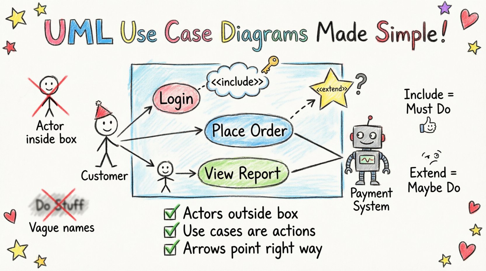
- Is the System an Actor? No. The system is the box containing the use cases. The actor is external to the system boundary.
- Is a Department an Actor? Generally, no. Actors represent individuals or roles. A “Sales Department” is too broad. Use “Sales Representative” instead.
- Is Another System an Actor? Yes. If an external application interacts with your system, it is modeled as an actor. For example, a Payment Gateway system interacting with an E-commerce platform.
- Can an Actor Be a Time Trigger? Yes. Sometimes a scheduled process is represented as a time actor, though this is less common in basic diagrams.
When in doubt, ask: “Does this entity initiate an action or receive a result from the system?” If yes, it is an actor. If no, it is likely part of the internal system or a data object.
🔗 Mastering Relationships: Include vs. Extend vs. Generalization
Relationships define the flow of behavior between use cases and actors. Beginners often mix these up, leading to diagrams that suggest optional behavior where there is mandatory behavior, or vice versa. Let us break down the three primary relationships.
1. Association (The Basic Link)
This is a simple line connecting an actor to a use case. It indicates that the actor initiates the use case. It is the foundation of the diagram. Every use case that is triggered by an actor must have an association line.
2. Include Relationship (The Mandatory Step)
An include relationship means that one use case must incorporate the behavior of another use case. It is a way to reuse common functionality without cluttering the main flow.
- When to use: When a specific step is required for multiple use cases.
- Example: “Place Order” includes “Validate Credit Card”. You cannot place an order without validating the card.
- Direction: The arrow points from the base use case (Place Order) to the included use case (Validate Credit Card).
3. Extend Relationship (The Optional Step)
An extend relationship means that one use case may incorporate the behavior of another, but only under specific conditions.
- When to use: When there is optional behavior or error handling.
- Example: “View Account” is extended by “View Transaction History”. You can view the account without viewing history, but you can choose to.
- Direction: The arrow points from the extending use case (View History) to the base use case (View Account).
4. Generalization (Inheritance)
This relationship allows a use case or actor to inherit the characteristics of another. It is similar to object-oriented inheritance.
- Actor Generalization: A “Manager” actor is a specialized version of a “Employee” actor. The Manager inherits all permissions of the Employee plus specific ones.
- Use Case Generalization: A “Login” use case might be generalized into “Login via Password” and “Login via Biometric”.
📦 Defining the System Boundary
The system boundary is the rectangle that encloses the use cases. It is the line that separates the system from the outside world. This is critical for defining scope.
Rules for System Boundaries
- Everything inside is part of the system: If it is inside the box, the system handles it.
- Everything outside is external: Actors, databases, and other systems sit outside.
- Do not include actors inside: Actors must always be outside the boundary.
- Do not include data objects inside: Data is usually internal, but use cases represent the action, not the storage.
Beginners often draw the boundary too tightly, excluding external systems that interact with the software, or too loosely, including actors like “The Customer” inside the box. Remember, the boundary defines the software you are building, not the people using it.
📊 Common Pitfalls and Corrections
To further clarify these concepts, here is a structured comparison of common errors versus the correct approach. Reviewing this table can help you self-correct your diagrams.
| Common Mistake | Why It Is Incorrect | Correct Approach |
|---|---|---|
| Putting the System inside the box | The box is the system. Putting the label “System” inside is redundant and confusing. | Label the box with the Project Name or leave it unlabeled. Focus on the use cases inside. |
| Using “Extend” for mandatory steps | Extend implies optionality. Mandatory steps should not be optional. | Use “Include” for mandatory steps. Use “Extend” for optional features like “Save Draft”. |
| Drawing lines crossing the boundary | Flows should not cross the system boundary arbitrarily. | Ensure association lines connect actors to use cases directly, without crossing the rectangle edge randomly. |
| Naming Use Cases as Verbs | Use cases should be noun phrases or gerunds to represent a unit of value. | Use “Place Order” instead of “Click Button”. Use “Login” instead of “Type Password”. |
| Ignoring Non-Functional Requirements | Use cases focus on functionality, not performance. | Note performance requirements in the description or notes, not as separate use cases. |
🧠 Deep Dive: The “What If” Scenarios
Sometimes the logic is not immediately obvious. Here are specific scenarios that often cause hesitation during the design phase.
Scenario 1: The Subsystem Interaction
Imagine a banking system where “Transfer Money” requires checking the account balance and checking the destination account validity. You might want to create separate use cases for these checks.
- Option A: Create “Check Balance” as a separate use case and include it in “Transfer Money”.
- Option B: Keep “Transfer Money” as a single atomic use case and describe the checks in the detailed description below the diagram.
Recommendation: If the balance check is complex and used elsewhere (like in “View Balance”), make it a separate use case. If it is only used for transfer, keep it in the description. This reduces diagram clutter.
Scenario 2: The Multiple Actors
What if a “Customer” and an “Administrator” both access “View Report”?
- Draw the “View Report” use case once.
- Draw an association line from “Customer” to “View Report”.
- Draw an association line from “Administrator” to “View Report”.
This shows that the functionality is the same, but the actors differ. Do not create two “View Report” use cases unless the behavior changes significantly based on the actor.
Scenario 3: The “Admin” Actor
It is common to see a generic “Admin” actor. However, this often hides important distinctions.
- An “Admin” who configures settings is different from an “Admin” who approves transactions.
- Consider splitting these into “System Administrator” and “Business Approver”.
- This distinction helps in defining security roles later in the development process.
📝 Validation Checklist
Before finalizing your diagram, run through this checklist to ensure accuracy. This step prevents rework during the development phase.
- Actor Check: Are all actors outside the system boundary?
- Verb Check: Are all use case names action-oriented (e.g., “Register User”)?
- Completeness Check: Does every actor have at least one use case? An isolated actor indicates a design error.
- Loop Check: Are there circular dependencies? Use Case A includes B, which includes A. This creates a logical loop.
- Granularity Check: Are the use cases at the right level? Too high (“Manage System”) is vague. Too low (“Click Button”) is implementation detail.
- Relationship Check: Do all arrows point in the correct direction? Include points to the included part. Extend points to the base.
- Scope Check: Does the diagram clearly show what is in scope for this specific project?
🌐 Functional vs. Non-Functional Requirements
A frequent point of confusion is whether to map non-functional requirements (NFRs) onto the Use Case Diagram. NFRs include performance, security, reliability, and usability.
Best Practice for NFRs
Do not create a use case for “System Must Load in 2 Seconds”. This is a constraint, not a user goal. Instead:
- Keep the diagram focused on functionality.
- Attach NFRs as notes or tags to specific use cases.
- Example: Add a note to “Generate Report” stating “Must complete within 5 seconds”.
This keeps the diagram clean and readable. If you clutter the diagram with performance metrics, stakeholders will lose focus on what the system actually does.
🔍 Troubleshooting Ambiguity
Even with the rules, ambiguity can creep in. Here are strategies to resolve unclear areas.
1. The “Who” Question
If you are unsure if an entity is an actor, ask: “Can this entity initiate a request?” If the answer is no, it is not an actor. For example, a “Database” does not initiate requests. It responds to them. It is part of the internal architecture, not an actor.
2. The “What” Question
If a use case name is vague (e.g., “Process Data”), ask: “What is the specific value delivered?” “Process Data” might be “Validate Data”, “Archive Data”, or “Export Data”. Break it down until you find the specific value.
3. The “How” Question
Do not model the implementation method. “Click Button” is a “How”. “Submit Form” is a “What”. Use Case Diagrams are abstract. They describe the interface, not the UI controls.
🏁 Final Thoughts on Design Accuracy
Building a Use Case Diagram is an iterative process. You will rarely get it perfect on the first draft. The value lies in the discussion it sparks with stakeholders. When you show a diagram, ask questions like “Is this the right boundary?” or “Did we miss any actors?”.
By focusing on the roles, the boundaries, and the relationships, you create a model that is both technically sound and business-relevant. Avoid the temptation to over-complicate with too many relationships. A simple diagram that is understood by all parties is better than a complex one that confuses everyone. Keep the focus on the user’s journey through the system, and the diagram will serve its purpose effectively.
Remember, this is a communication tool. Its primary job is to ensure everyone agrees on what the system is supposed to do before a single line of code is written. Take your time with the actors and the scope. Once those are solid, the rest of the software design becomes much clearer.