
Requirements engineering is often where projects go to die. It is the graveyard of good intentions, buried under layers of ambiguous language and misunderstood expectations. Stakeholders walk into meetings with a vision in their heads, but what they say often lacks the precision needed to build a robust system. They speak in terms of “needs,” “wants,” and “maybe later.” This linguistic vagueness leads to scope creep, budget overruns, and software that fails to solve the actual problem.
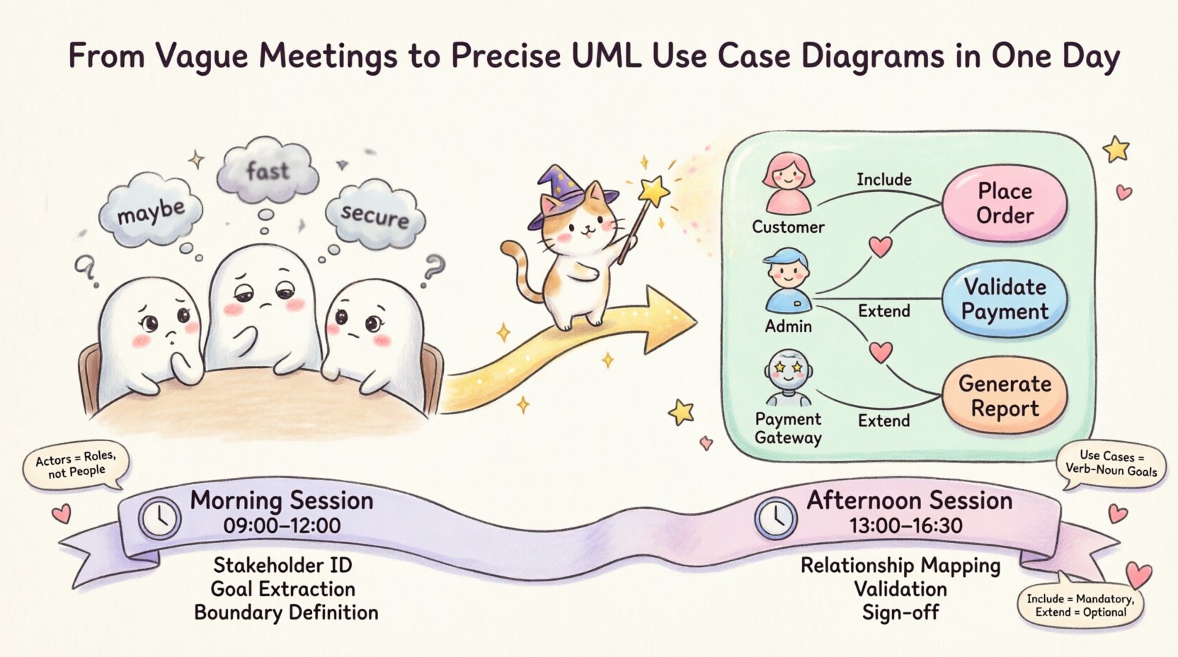
This guide details a specific transformation: taking chaotic, vague stakeholder input and converting it into a structured, unambiguous UML Use Case Diagram within a single day. This is not about magic or speed; it is about discipline, structured questioning, and the rigorous application of the Unified Modeling Language (UML) standard. By the end of this document, you will understand how to extract the core logic of a system from the noise of conversation.
🧩 The Ambiguity Trap: Why Meetings Fail
Most requirement gathering sessions suffer from a fundamental disconnect. The business side speaks in outcomes and value, while the technical side speaks in logic and data flow. When these two languages collide without a translation layer, the result is confusion. Stakeholders often describe features rather than functions. They say, “I need a button that does X,” without defining what X actually entails in the context of the system.
Common symptoms of vague requirements include:
- Subjective Language: Terms like “fast,” “easy,” or “secure” are interpreted differently by every team member.
- Missing Actors: The system is built for the primary user, but secondary users or external systems are forgotten until deployment.
- Undefined Boundaries: It is unclear what the system does and what lies outside its scope.
- Hidden Logic: Complex business rules are assumed to be simple, only to be discovered during testing.
Without a visual artifact to anchor the discussion, these ambiguities persist. A Use Case Diagram provides that anchor. It forces the team to define the scope and the interactions explicitly. It turns “I want the system to handle orders” into a distinct interaction between an “Order Actor” and an “Order System.” This shift from narrative to structure is the first step toward precision.
🏗️ Anatomy of the UML Use Case Diagram
To build a diagram that holds weight, you must understand the components. A Use Case Diagram is not just a drawing; it is a map of functionality. It defines the “what” of the system, separate from the “how.” This separation is crucial for maintaining flexibility in design.
The core elements include:
- Actors: These represent the roles that interact with the system. They are not specific individuals but rather roles, such as “Admin,” “Customer,” or “External Payment Gateway.” An actor can be a human or another system.
- Use Cases: These are the functional units of the system. They represent a specific goal achieved by an actor. For example, “Place Order” or “Generate Report.” Each use case is a discrete unit of value.
- System Boundary: This defines the scope of the project. Everything inside the box is the responsibility of the system. Everything outside is external context.
- Relationships: These define how actors and use cases interact. Key relationships include Association, Include, Extend, and Generalization.
Understanding these elements prevents the common error of drawing flowcharts instead of use cases. A flowchart shows the steps to complete a task. A use case diagram shows the functional capabilities available to the user. Confusing the two leads to diagrams that are too detailed and lose their high-level overview purpose.
📅 The One-Day Protocol: A Step-by-Step Transformation
Transforming a day of vague meetings into a precise diagram requires a structured agenda. You cannot simply sit down and draw. You must facilitate a workshop that guides the stakeholders through the process of definition. The following schedule outlines how to execute this transformation effectively.
Morning Session: Discovery and Elicitation
The morning is dedicated to extracting information from the stakeholders. The goal is to identify the actors and the high-level goals. Do not get bogged down in details yet.
- 09:00 – 10:00: Stakeholder Identification: Ask, “Who interacts with this system?” List every role. Distinguish between primary actors (start the interaction) and secondary actors (provide support).
- 10:00 – 11:30: Goal Extraction: For each actor, ask, “What is the primary goal of this role?” Capture these as potential use cases. Avoid technical jargon here; stick to business goals.
- 11:30 – 12:00: Boundary Definition: Draw a box on a whiteboard. Place the identified use cases inside. Ask, “Is this functionality inside the system or handled externally?” This clarifies scope immediately.
Afternoon Session: Structuring and Refining
The afternoon is for connecting the dots and defining relationships. This is where the vague becomes precise.
- 13:00 – 14:30: Relationship Mapping: Connect actors to use cases with lines. Identify where one use case is necessary for another (Include) or where a variation occurs (Extend).
- 14:30 – 15:30: Validation Walkthrough: Walk through the diagram with the stakeholders. Ask, “If I am this actor, can I achieve this goal using this diagram?” If they say no, add the missing link.
- 15:30 – 16:30: Review and Sign-off: Finalize the notation. Ensure all labels are clear. Confirm that the diagram represents the agreed-upon scope.
🛠️ Common Pitfalls and Solutions
Even with a structured plan, errors occur. The following table outlines common mistakes made during the diagramming process and the corrective actions required.
| Pitfall | Description | Corrective Action |
|---|---|---|
| System Function as Actor | Labeling a function like “Login System” as an actor. | Actors are external. Change to “User” or “Authentication Service” as the actor. |
| Too Many Details | Attempting to show every step of a process in the diagram. | Usecase diagrams show goals, not steps. Move detailed steps to Activity Diagrams. |
| Missing External Systems | Focusing only on human users. | Identify all external dependencies, such as APIs or legacy databases, as actors. |
| Confusing Include vs. Extend | Mixing mandatory dependencies with optional variations. | Include is mandatory for the base use case. Extend is optional behavior triggered by specific conditions. |
| Ambiguous Labels | Using nouns instead of verb-noun phrases for use cases. | Ensure every use case is a verb-noun pair, e.g., “Process Payment” instead of “Payment.” |
🔍 Deep Dive: Relationships Explained
The power of the UML Use Case Diagram lies in the relationships between its elements. Understanding the difference between Include and Extend is critical for accurate modeling.
An Include relationship indicates that one use case must always happen when another happens. It is a mandatory dependency. For example, “Place Order” might include “Validate Payment.” You cannot place an order without validating payment. This helps in modularizing the requirements.
An Extend relationship indicates optional behavior. It extends the functionality of a base use case under specific conditions. For example, “Apply Discount” might extend “Place Order.” This only happens if the customer has a coupon code. This distinction keeps the base diagram clean while capturing complexity where needed.
Another vital relationship is Generalization. This allows you to create inheritance hierarchies. If you have a “Premium Customer” and a “Standard Customer,” both of which can “Place Order,” you can generalize the “Customer” actor. The “Place Order” use case remains connected to the base actor, while specific behaviors are added to the child actors. This reduces redundancy and clarifies the system structure.
🛡️ Validation and Maintenance
Creating the diagram is only half the battle. The diagram must remain accurate as the project evolves. A diagram that sits in a folder and is never updated becomes a liability. It misleads developers and stakeholders alike.
To maintain accuracy, adopt the following practices:
- Version Control: Treat the diagram as code. Store it in a repository. Record changes and the rationale behind them.
- Review Cycles: Schedule regular reviews. Whenever a requirement changes, check if the diagram needs updating.
- Living Document: Use the diagram during sprint planning. If a task does not map to a use case, question why it exists.
- Clarity Check: Ensure labels remain descriptive. If a stakeholder asks, “What does this line mean?” the diagram has failed.
🚀 The Value of Precision
Why invest the time to create a precise diagram? The return on investment is measured in reduced rework. When requirements are ambiguous, developers make assumptions. When assumptions are wrong, code must be rewritten. A Use Case Diagram serves as a contract of understanding. It aligns the technical team with the business stakeholders.
Furthermore, it aids in test case generation. Every use case represents a potential test scenario. If you have “Generate Report,” the test team knows to verify that reports can be generated under various conditions. This traceability ensures that nothing is built that was not requested, and nothing requested is left untested.
The transition from vague meetings to precise diagrams is a shift in mindset. It requires discipline to resist the urge to start coding or designing screens before the logic is solidified. It requires the confidence to ask “What exactly do you mean?” even when stakeholders are pushing for speed. This discipline pays dividends throughout the development lifecycle.
📝 Summary of Key Takeaways
- Define Actors Clearly: Distinguish between human roles and external systems.
- Focus on Goals: Use cases represent goals, not steps or screens.
- Set Boundaries: Clearly mark what is inside and outside the system.
- Map Relationships: Use Include and Extend to manage complexity.
- Validate Continuously: Keep the diagram updated as requirements evolve.
By adhering to these principles, you can transform a day of uncertainty into a foundation of clarity. The UML Use Case Diagram is a tool for communication, not just documentation. When used correctly, it bridges the gap between human intent and machine execution. It turns the chaos of requirements into a structured plan of action.